A push rod device for electric vehicle battery replacement

A push rod device, electric vehicle technology, applied in the direction of electric power plant, power plant, vehicle parts, etc., can solve the problem of small thrust and so on

Active Publication Date: 2017-02-08
XJ ELECTRIC +1
View PDF5 Cites 0 Cited by
  • Summary
  • Abstract
  • Description
  • Claims
  • Application Information

AI Technical Summary

Problems solved by technology

[0003] The purpose of the present invention is to provide a push rod device that can meet the needs of extracting the battery box of an electric vehicle, so as to solve the problem that the thrust provided by the electric push rod device is relatively small

Method used


Image

  • A push rod device for electric vehicle battery replacement
  • A push rod device for electric vehicle battery replacement
  • A push rod device for electric vehicle battery replacement

Examples


Embodiment Construction

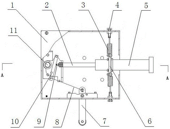
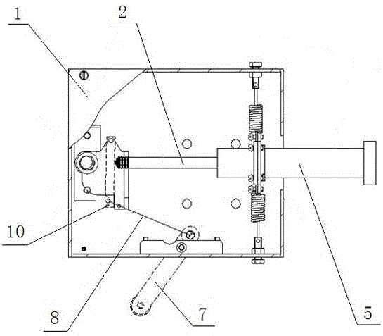
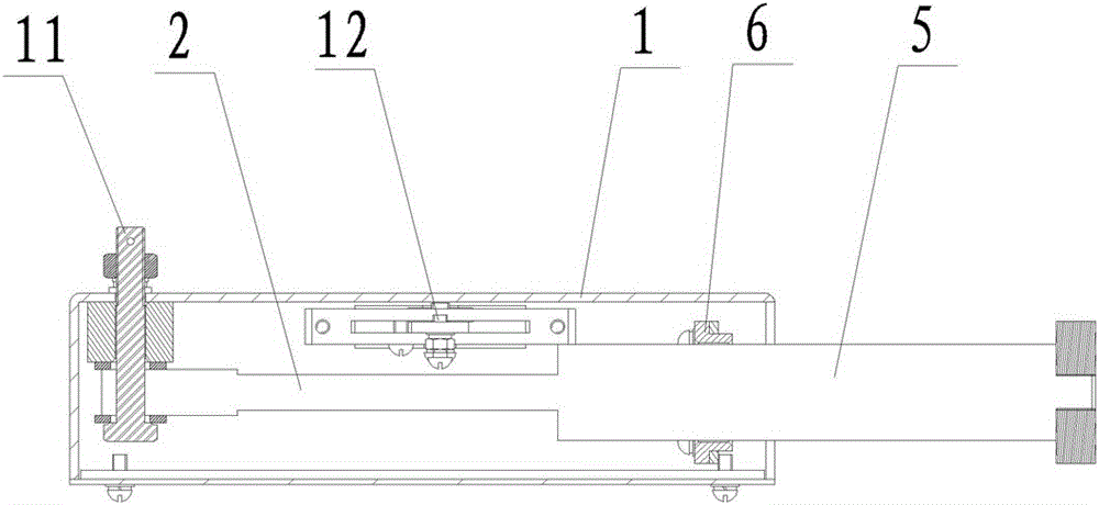
[0013] The embodiment of push rod device of the present invention: as Figure 1-4 As shown, it includes a housing 1, and the housing 1 is provided with a lockable gas spring whose axis extends along the front and rear directions. The gas spring is an existing equipment, mainly composed of a gas spring cylinder 5, a gas spring piston rod 2 and a gas spring button 9 Composition, wherein the gas spring button 9 is used to control the expansion and contraction of the gas spring, and the gas spring button 9 is controlled by the crank arm pressure plate 10 to press down or pop up; the end of the gas spring piston rod 2 passes through the first pin extending along the vertical axis The shaft 11 is hinged in the housing 1, the end of the gas spring cylinder 5 protrudes from the front side wall of the housing, and a front support for supporting the gas spring cylinder 5 is also provided in the housing 1, and the front support and the gas spring cylinder Body 5 guiding sliding fits, by ...


PUM


Abstract

The invention discloses a push rod device for switching power for an electric automobile. The push rod device comprises a shell and a lockable air spring, wherein the axis of the lockable air spring extends along the forward-backward direction; the tail end of a piston rod of the air spring is hinged to the shell; the tail end of an air spring cylinder extends forwards out of the shell to form a force application end for pushing a battery box; a front support which is matched with a sliding support of the air spring cylinder is arranged in the shell; and the shell is also provided with a control mechanism for controlling opening and closing of an air spring button. Since the air spring is adopted in the shell, the forward-backward stretch of the air spring cylinder is realized under the control effect of the control mechanism, the thrust produced thereby is sufficient to meet the requirements of draw-out of the battery box, and the battery box can be pushed in smoothly even though the battery box is blocked.

Description

technical field [0001] The invention relates to the field of electric vehicle charging, in particular to a push rod device for changing battery boxes at an electric vehicle charging station. Background technique [0002] At present, in the electric vehicle charging station of the State Grid, in order to ensure the successful extraction of the battery box, a push rod mechanism is generally used. The thrust of the current push rod mechanism is mainly provided by ordinary mechanical springs. Due to the limitation of structural space, spring processing technology and Influenced by the service life of the mechanical spring, the thrust is generally small, so when the battery box is stuck, it is difficult to push the battery box in, which will cause the failure of battery replacement; in addition, the push rod of this push rod mechanism can only be straight Movement, once the battery box is tilted, it is easy to cause the push rod to be twisted and deformed. Contents of the inven...

Claims


Application Information

Patent Timeline
Patent Type & Authority Patents(China)
IPC IPC(8): B60S5/06
Inventor 于文斌陈天锦韩海伦陈晓楠郝战铎胡新举丁习坤宋兵兵于国鼎罗发强杨昌富胡宝陈洪杰詹金果石伟
Owner XJ ELECTRIC
Why Eureka
Try Eureka