Eureka AIR delivers breakthrough ideas for toughest innovation challenges, trusted by R&D personnel around the world.

Tilting double-duct subminiature unmanned plane

An unmanned aerial vehicle, ultra-small technology, applied in the direction of rotorcraft, motor vehicles, aircraft parts, etc., can solve the problems of poor safety, relatively low flight speed requirements, high cost, etc., to achieve good reliability and stability, excellent air quality The effect of shifting performance and good starting performance

Inactive Publication Date: 2013-10-02
SHANGHAI UNIV
View PDF6 Cites 21 Cited by
  • Summary
  • Abstract
  • Description
  • Claims
  • Application Information

AI Technical Summary

Problems solved by technology

Based on the analysis of two new types of aircraft, the tilt-rotor aircraft and the ducted fan aircraft, and combining the advantages of both, a new type of aircraft type is studied to solve the existing two-rotor airflow interference of the tilt-rotor aircraft. Problems such as low efficiency and safety, as well as improving the aerodynamic complexity of the existing ducted aircraft vector propulsion system, and overcoming the serious coupling of traditional unmanned helicopter flight control, poor safety caused by exposed rotor blades, high noise, and cost A series of advanced problems, and based on the research of ultra-small UAV systems on aircraft, and finally apply the ultra-small UAV system to complex environments such as cities. Such environments have relatively low requirements for the flight speed of ultra-small UAV systems. High, but higher requirements are put forward for the safety and flight efficiency of ultra-small UAV systems

Method used


Image

  • Tilting double-duct subminiature unmanned plane
  • Tilting double-duct subminiature unmanned plane
  • Tilting double-duct subminiature unmanned plane

Examples


Embodiment Construction

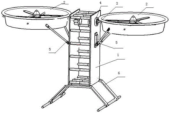
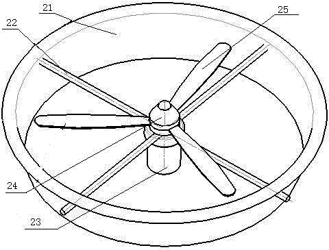
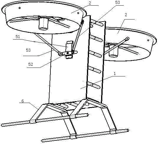
[0020] like figure 1 As shown, a tilting double-duct ultra-small unmanned aerial vehicle includes a fuselage 1, a double-duct fan aircraft 2, a tilting shaft 3, a rotating mechanism 4, a duct tilting mechanism 5, landing gear 6 and a flight Control system, the central cavity of the fuselage 1 is equipped with a flight control system, the double-duct fan aircraft 2 is connected with the rotation mechanism 4 through the tilting shaft 3, the rotation mechanism 4 is installed on the fuselage 1, and the duct Type fan aircraft 2 are symmetrically distributed on both sides of fuselage 1, duct tilt mechanism 5 is connected with duct type fan aircraft 2, duct type tilt mechanism 5 is installed on fuselage 1, and landing gear is installed on the lower end of fuselage 1 6. The double-ducted fan aircraft 2 and the ducted tilting mechanism 5 are respectively connected to the flight control system, and the left-right symmetrical two double-ducted fan aircraft 2 can be controlled by the duct...


PUM


Abstract

The invention discloses a tilting double-duct subminiature unmanned plane adopting a vector boosting principle. The tilting double-duct subminiature unmanned plane is characterized in that a central inner cavity of a machine body is provided with a control system of the whole aircraft, double-duct fan aircrafts are connected with a machine body through a tilting shaft and are symmetrically distributed on the two sides of the machine body; and duct tilting mechanisms are distributed at positions of the machine body connected with the tilting shaft, a lifting frame is arranged below the machine body, and the duct tilting mechanisms and the duct fan aircrafts are respectively connected with a flight control system. The tilting double-duct subminiature unmanned plane provided by the invention has the advantages that left and right ducts are symmetrically distributed relative to the machine body, so as to respectively generate pull force for enabling the aircrafts to ascend, the left and right ducts can rotate relative to the machine body under the control of the tilting system, so that the aircrafts can change postures conveniently; since the ducts adopt rotor ring design, the plane has higher flying efficiency and higher safety; and the tilting double-duct subminiature unmanned plane has wide application prospect in the fields such as low-altitude reconnaissance and atmospheric environmental monitoring under complex environment in a city.

Description

technical field [0001] The invention relates to an ultra-small flying robot, in particular to a tilting double-duct ultra-small unmanned aerial vehicle. Background technique [0002] The UAV system has the advantages of low cost, small size, easy to carry, small take-off and landing space, etc., and has a certain load capacity and wind resistance. Applications include research, traffic patrolling, and city surveillance. [0003] At present, relatively mature ultra-small UAVs mainly have two structural forms: fixed-wing and rotary-wing. The two types of ultra-small UAVs have different characteristics. Long distance and other advantages, but the mobility is insufficient, in addition, it also needs a wide platform for take-off and landing. The rotor ultra-small UAV has good maneuverability, and can achieve fixed-point low-altitude hovering, and can perform various complex low-altitude flight operations. It is more complex and belongs to a single point of failure system, whic...

Claims


Application Information

Patent Timeline
Patent Type & Authority Applications(China)
IPC IPC(8): B64C27/22B64C13/00B64C27/20
Inventor 高同跃王冬冬费涛葛海浪
Owner SHANGHAI UNIV
Why Eureka
Eureka Blog
Learn More