
Bridge pier and construction method thereof

A bridge pier and pier column technology, applied in the field of civil engineering bridges, can solve problems affecting the durability of structures, corrosion of prestressed steel cables and anchors, and difficulties in concrete maintenance

Inactive Publication Date: 2013-10-02
CHONGQING JIAOTONG UNIVERSITY +1
View PDF6 Cites 5 Cited by
  • Summary
  • Abstract
  • Description
  • Claims
  • Application Information

AI Technical Summary

Problems solved by technology

[0004] Although the bridge piers of the above structure can support the bridge body, because they are completely reinforced concrete structures, the bridge piers of this structure also have certain defects: first, the weight of the bridge pier cover girder completely composed of reinforced concrete is relatively heavy. Secondly, the bridge pier completely composed of reinforced concrete structure needs to erect supports on site during construction. The construction cost is relatively high. In addition, there are disadvantages such as high risk of working at heights and difficulty in concrete maintenance. Thirdly, since micro-cracks in general concrete are inevitable, the use of transverse prestressed structures or no transverse prestressed bridge pier cap beams cannot completely avoid micro-cracks The problem of waterproofing often leads to corrosion of steel bars, prestressed steel cables and anchors on bridge piers, which affects the durability of the structure

Method used


Image

  • Bridge pier and construction method thereof
  • Bridge pier and construction method thereof
  • Bridge pier and construction method thereof

Examples


Embodiment Construction

[0073] The first object of the present invention is to provide a bridge pier to reduce the influence of the self-weight of the bridge pier cap girder on its working load. The second object of the present invention is to provide a construction method for the above bridge pier.

[0074] The following will clearly and completely describe the technical solutions in the embodiments of the present invention with reference to the accompanying drawings in the embodiments of the present invention. Obviously, the described embodiments are only some, not all, embodiments of the present invention. Based on the embodiments of the present invention, all other embodiments obtained by persons of ordinary skill in the art without making creative efforts belong to the protection scope of the present invention.

[0075] In this embodiment, for the convenience of description, the horizontal direction in the following content refers to the direction along the width of the bridge, "up" and "down" r...


PUM


Abstract

The invention provides a bridge pier, which comprises a capping beam and pier studs, wherein the capping beam comprises a steel truss fixedly connected with the pier studs, and concrete panels; the concrete panels are arranged on the top of the steel truss, are prefabricated in a multi-subblock mode and are spliced to form a whole; an FRP (fiber reinforce plastic) cloth felt combination structure covers the steel truss; prestress cables are arranged in the concrete panels prefabricated and formed by multiple subblocks; and the concrete panels are tensioned and connected into a whole by the prestress cables. According to the bridge pier capping beam with the structure, the FRP cloth felt combination structure covering the steel truss and the combination structure formed by the concrete panels prefabricated by multiple subblocks are used for replacing the original solid structure of the reinforced concrete so as to lower the self weight of the bridge pier capping beam, and therefore the bridge pier capping beam can bear a bridge body with a bigger load. In addition, according to the capping beam with the combination structure of the steel truss and the concrete panels, the use amount of cast-in-place concrete is reduced so as to simplify the construction process of the bridge pier, shorten the construction period and reduce the difficulty. The FRP structure is free from maintaining and has a higher durability. The invention also relates to a construction method for the bridge pier.

Description

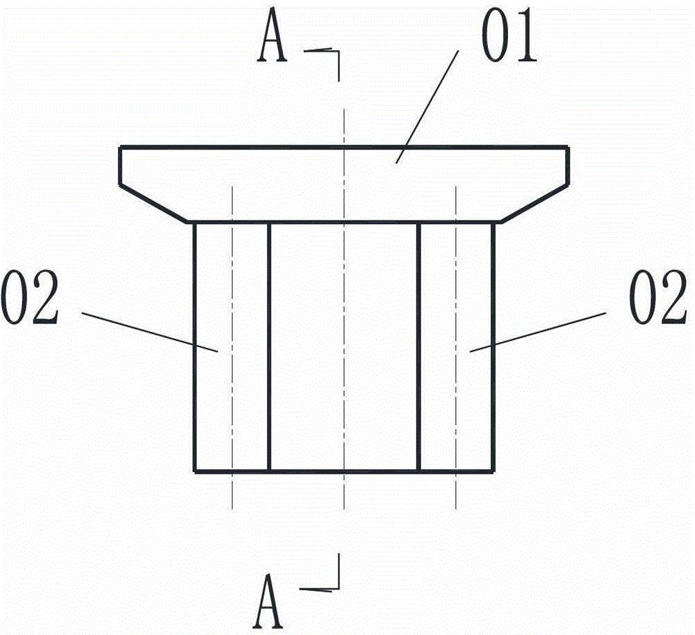
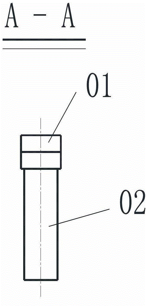
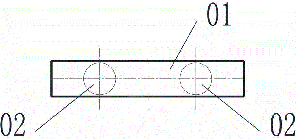
technical field [0001] The present invention relates to the technical field of civil engineering bridges, more specifically, to a bridge pier, and also relates to a construction method for the above-mentioned bridge pier. Background technique [0002] Reinforced concrete column piers are the light-weight pier forms widely used at present, and the structure of cylindrical or square column piers is more common. Bridge piers are generally arranged as a single column, two columns or three columns along the width direction of the bridge, and two columns are the most common. [0003] Such as Figure 1-Figure 3 As shown (taking the form of setting two columns as an example), the pier in the prior art includes a cover beam 01 and a pier column 02, wherein the cover beam 01 is arranged on the pier column 02 for contacting with the bridge body to Support the bridge body. The cover beam 01 and pier column 02 generally adopt reinforced concrete structure, and some bridges apply transv...

Claims


Application Information

Patent Timeline
Patent Type & Authority Applications(China)
IPC IPC(8): E01D19/02E01D21/00E01D101/28
Inventor 吴国松胡嘉鸿
Owner CHONGQING JIAOTONG UNIVERSITY
Learn More