
Single-bottom adjustable valve bottom cleaning drill

An adjustable valve technology, which is applied in the direction of earthwork drilling, wellbore/well components, etc., can solve the problems that the thickness of the sediment does not meet the ideal requirements, it is not easy to clean the sediment, and affects the effect and progress of the removal of slag, so as to save Closing time, saving materials, and avoiding the effect of sediment leakage

Active Publication Date: 2013-10-02
四川四海达通工程机械有限公司
View PDF9 Cites 7 Cited by
  • Summary
  • Abstract
  • Description
  • Claims
  • Application Information

AI Technical Summary

Problems solved by technology

The drill bucket of this structure has the following disadvantages: 1. The through hole opening into the drill body is fixed, and the size of the through hole cannot be adjusted arbitrarily, and the particle size of the slag entering is limited, which affects the effect and progress of slag cleaning; 2. After cleaning the slag, it is also necessary to turn the drill bucket counterclockwise to close the through hole, which is easy to cause the slag to leak back, and the thickness of the remaining slag after cleaning cannot meet the ideal requirements; 3. The soil collecting plate is very wide and thick, and the soil entry steps are relatively high. It is not easy to clean up the sediment when shoveling

Method used


Image

  • Single-bottom adjustable valve bottom cleaning drill
  • Single-bottom adjustable valve bottom cleaning drill
  • Single-bottom adjustable valve bottom cleaning drill

Examples


Embodiment Construction

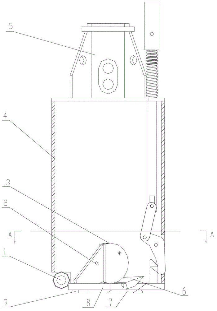
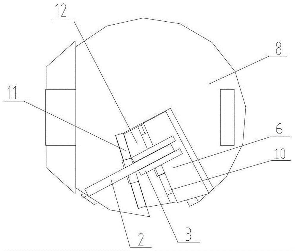
[0015] see Figure 1-Figure 5 , the present invention comprises ladle body 4 and the clear bottom plate 8 of ladle body 4 bottoms, has slag inlet on the clear bottom plate 8, and scraper 7 is installed below the clear bottom plate 8. Its key technology is that the bottom cleaning plate 8 is a single bottom cleaning bottom plate, and the valve mechanism is installed at the slag inlet on the bottom cleaning plate 8 through the second hinge 11. The valve mechanism includes a first cover plate 6 and a second cover plate 12, the first The cover plate 6 and the second cover plate 12 are connected by the first hinge 10, and a valve adjustment mechanism is installed on the bottom plate 8 corresponding to the valve mechanism. 2 arc-shaped limiting plates 3 connected.

[0016] Under the clear bottom plate 8, the soil drainage plate 9 is also installed.

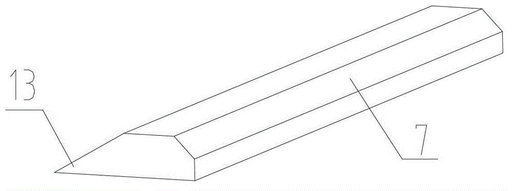
[0017] The cross-section of the scraper 7 is a wedge-shaped structure, and its soil entry end 13 is very thin, and the soil entry st...


PUM


Abstract

The invention provides a single-bottom adjustable valve bottom cleaning drill, and relates to devices used for removing slag from the bottom of a pile hole during engineering construction. The single-bottom adjustable valve bottom cleaning drill comprises a barrel body and a bottom cleaning plate at the bottom of the barrel body, wherein a scraping plate is mounted on the lower surface of the bottom cleaning plate. The key technology of the single-bottom adjustable valve bottom cleaning drill is that the bottom cleaning plate is a single-bottom bottom cleaning plate; a valve mechanism is mounted on the upper surface of the bottom cleaning plate in the position of a slag inlet, and comprises a first cover plate and a second cover plate; the first cover plate and the second cover plate are connected with each other through a first hinge; a valve adjusting mechanism is mounted on the bottom cleaning plate in a position corresponding to the valve mechanism. The single-bottom adjustable valve bottom cleaning drill has the benefits that only one layer of drill bit baseplate is provided, so that the earth inlet step of the structure is 3 cm to 4 cm lower than that of a 'double-bottom bottom cleaning drill', which provides a favorable condition for meeting the requirement that the sediment thickness is lower than 5 cm; as only one layer of baseplate is provided to form the 'single-bottom bottom cleaning drill', the phenomenon that two baseplates of the 'double-bottom bottom cleaning drill' are connected with each other through a drilling bucket main body is eliminated, which not only saves material, but also simplifies the structure of a drilling tool, and reduces the cost and the failure rate of the drilling tool.

Description

Technical field: [0001] The utility model relates to a single bottom adjustable valve bottom cleaning drill, which relates to a device for cleaning slag at the bottom of a pile hole during engineering construction. Background technique: [0002] In pile construction, it is necessary to clean the sediment at the bottom of the pile hole, and the thickness requirements of the sediment at the bottom of the hole are different for different types of piles. Generally, wall protection piles and friction piles have lower requirements for sediment thickness (generally require sediment thickness < 10cm), while load-bearing piles have higher requirements (generally require sediment thickness < 5cm). At present, the commonly used equipment for hole forming (hole forming diameter: 0.6 meters to 3.5 meters) is a rotary drilling rig, and the bottom cleaning drilling tool generally used is a "double bottom bottom cleaning drill". For example, Patent No. 201220321627.3 discloses a "cle...

Claims


Application Information

Patent Timeline
Patent Type & Authority Applications(China)
IPC IPC(8): E21B27/00
Inventor 魏露吴文学
Owner 四川四海达通工程机械有限公司
Learn More