A magnetic levitation support for a refrigeration compressor
A refrigeration compressor and magnetic levitation technology, applied in the field of refrigeration compressors, can solve problems such as the inability to achieve shock absorption effect and the like
- Summary
- Abstract
- Description
- Claims
- Application Information
AI Technical Summary
Problems solved by technology
Method used
Image

Examples
Embodiment Construction
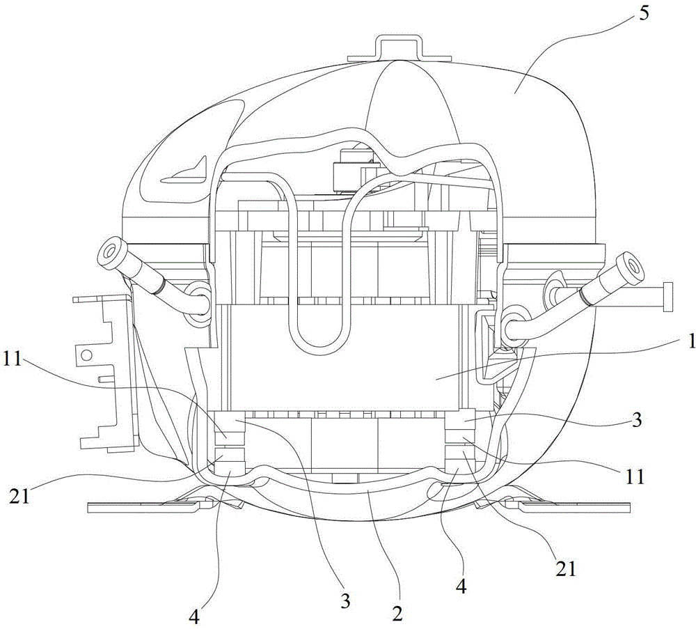
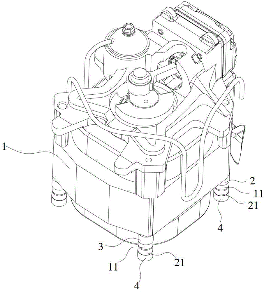
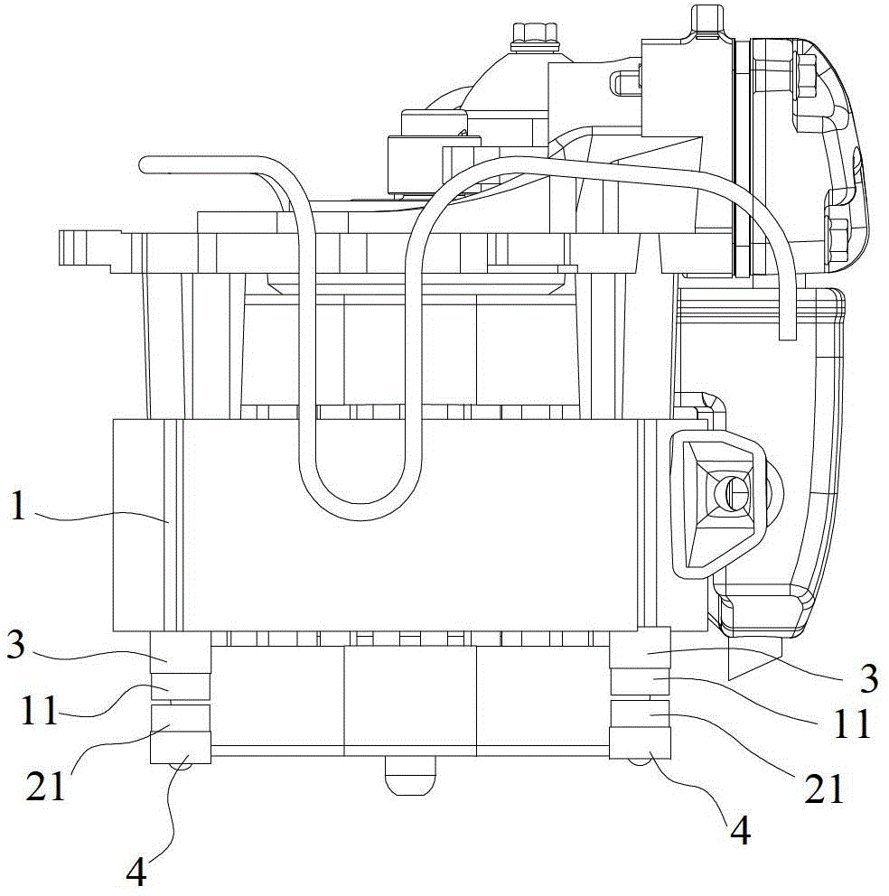
[0018] refer to Figure 1 to Figure 5 , the present invention provides a magnetic levitation support for a refrigeration compressor, which includes an upper magnet 11 arranged on the lower side of the core 1 and a lower magnet 21 arranged on the inner side of the lower shell 2, the upper magnet 11 and the lower magnet 21 are arranged facing each other with the same pole, The movement 1 is suspended above the lower case 2 .
[0019] The magnetic levitation support of this refrigeration compressor suspends the core 1 above the lower shell 2 through the mutual repulsion between the same poles of the upper magnet 11 and the lower magnet 21, so that the core 1 and the lower shell 2 are completely separated, and the gap between the core 1 and the shell There is no direct or indirect contact through the compression spring, that is, the transmission path of the vibration is completely blocked, so that the vibration of the movement 1 cannot be transmitted to the outside of the refriger...
PUM
 Abstract
Description
Claims
Application Information