Supercharge Your Innovation With Domain-Expert AI Agents!

Pedal motorcycle engine rack test method

A technology of engine bench and test method, which is applied in the direction of engine test, machine/structural component test, measuring device, etc., which can solve the problems of long period, complicated test process and high test cost

Inactive Publication Date: 2013-10-02
CHONGQING CONSTR ELECTROMECHANICAL CO LTD
View PDF7 Cites 2 Cited by
  • Summary
  • Abstract
  • Description
  • Claims
  • Application Information

AI Technical Summary

Problems solved by technology

[0003] In order to solve the technical problems in the prior art that multiple transmission ratios need to be calculated when carrying out the scooter engine bench performance test through the output shaft, resulting in complicated test process, long cycle and high test cost, the purpose of the present invention is to provide a A scooter engine bench test method with simple and reliable test process,

Method used


Image

  • Pedal motorcycle engine rack test method
  • Pedal motorcycle engine rack test method
  • Pedal motorcycle engine rack test method

Examples


Embodiment Construction

[0023] Below in conjunction with accompanying drawing, preferred embodiment of the present invention is described in further detail:

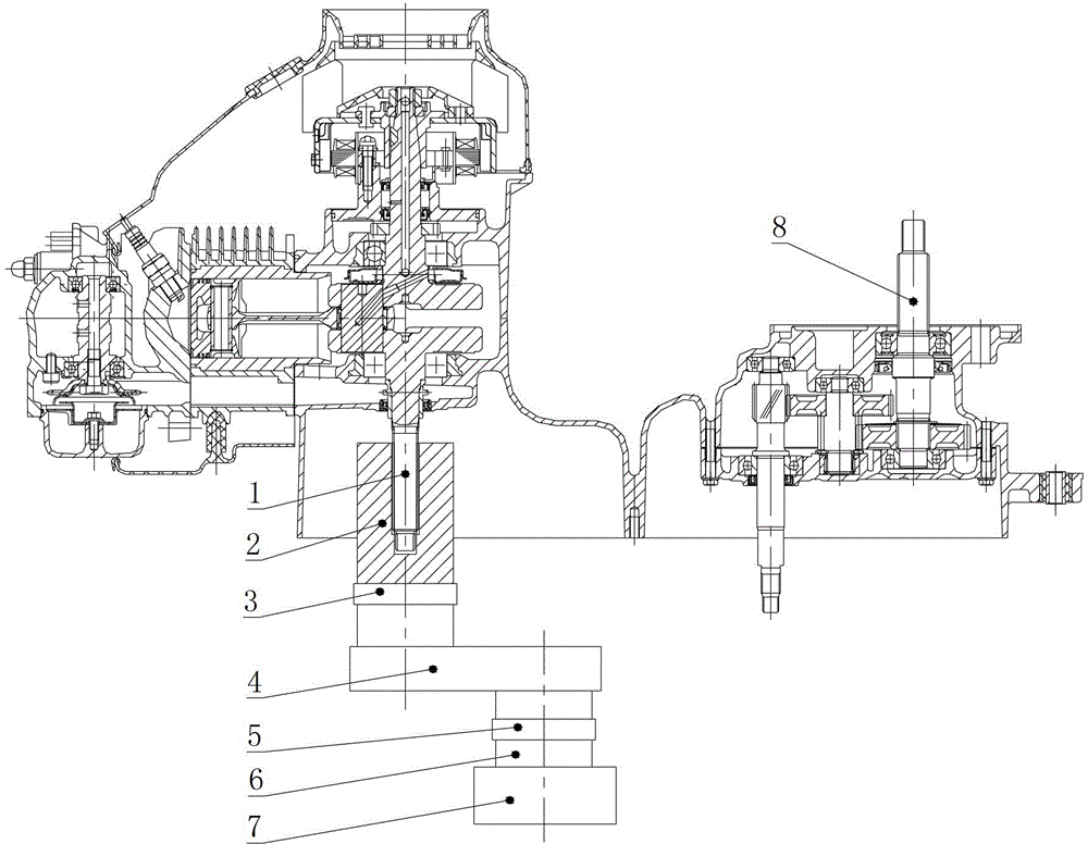
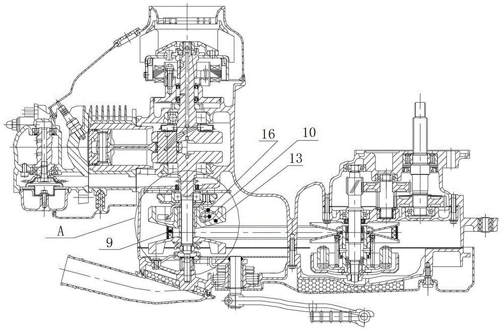
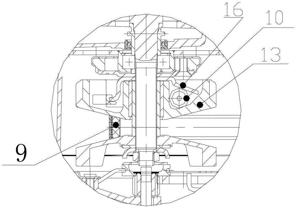
[0024] figure 2 It is a schematic diagram of the structure of the CVT part of the test engine, image 3 yes figure 2 Partial enlarged view at A in the center, such as figure 2 with image 3 Shown, the CVT part of scooter engine comprises belt 9, roller hammer 10, roller hammer pressing plate 16 and belt pulley 13, and scooter engine bench test method of the present invention comprises the steps:

[0025] Step 1. Design and manufacture the auxiliary bushing 11 for the test, and select the test belt 12 for the test;

[0026] Step 2. The belt 9 and roller 10 of the CVT part of the test engine are removed, the test belt 12 is installed on the front and rear belt pulleys, and the auxiliary bushing 11 is installed between the roller hammer pressure plate 16 and the belt pulley 13. On the crankshaft, the belt pulley 13 is released to ensure th...


PUM


Abstract

The invention relates to a pedal motorcycle engine rack test method. An auxiliary lining is mounted between a rolling hammer pressure plate and a belt pulley, so a transmission ratio between a crank shaft and an output shaft of a pedal motorcycle engine is fixed, a performance test of the pedal motorcycle engine can be conveniently carried out by utilizing the fixed transmission ratio. A performance test of a pedal motorcycle engine rack in the prior art is carried out through an output shaft, multiple transmission ratios are needed to calculate according to different test points, so the pedal motorcycle engine rack test method solves problems of complex test process, long test period and high test cost existing in the prior art.

Description

technical field [0001] The invention relates to a test method for a scooter engine, in particular to a performance test method for a scooter engine bench test. Background technique [0002] At present, there are mainly two methods for the scooter engine bench performance test, one is to use the direct test at the crankshaft 1; the other is to indirect test at the output shaft 8 after calculating the transmission ratio through each test point. Such as figure 1 As shown, using the first method, when the crankshaft 1 is directly tested, in order to avoid damage to the dynamometer when the engine fails, it is usually necessary to design a gearbox 4, and the input end of the gearbox 4 passes through the shock-absorbing rubber sleeve I3 It is connected with the engine crankshaft 1 with the coupling I2; the output end of the gearbox 4 is connected with the dynamometer 7 through the shock-absorbing rubber sleeve II5 and the coupling II6. When using this method, the number of parts...

Claims


Application Information

Patent Timeline
Patent Type & Authority Applications(China)
IPC IPC(8): G01M15/00
Inventor 陈志敏杨安芬曾凡镔
Owner CHONGQING CONSTR ELECTROMECHANICAL CO LTD
Features
  • R&D
  • Intellectual Property
  • Life Sciences
  • Materials
  • Tech Scout
  • Unparalleled Data Quality
  • Higher Quality Content
  • 60% Fewer Hallucinations
Learn More