LED display screen
A technology of LED display screen and display module, which is applied in the direction of instruments, identification devices, etc., can solve the problems of low production efficiency, time-consuming production, and difficult maintenance, so as to reduce disassembly and maintenance costs and improve production efficiency , The effect of facilitating front maintenance
- Summary
- Abstract
- Description
- Claims
- Application Information
AI Technical Summary
Problems solved by technology
Method used
Image

Examples
Embodiment Construction
[0021] The technical solutions of the present invention will be further described below in conjunction with the accompanying drawings and specific embodiments. It should be understood that the specific embodiments described here are only used to explain the present invention, not to limit the present invention.
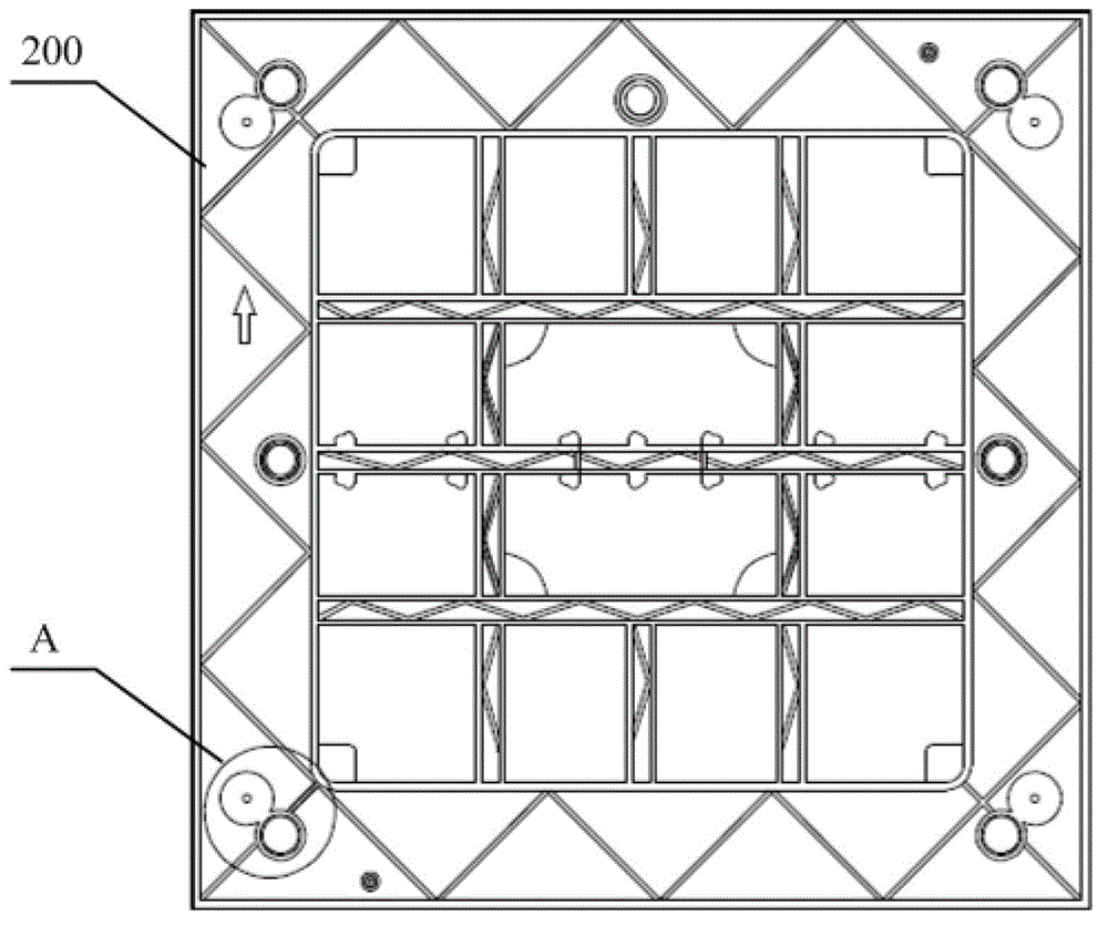
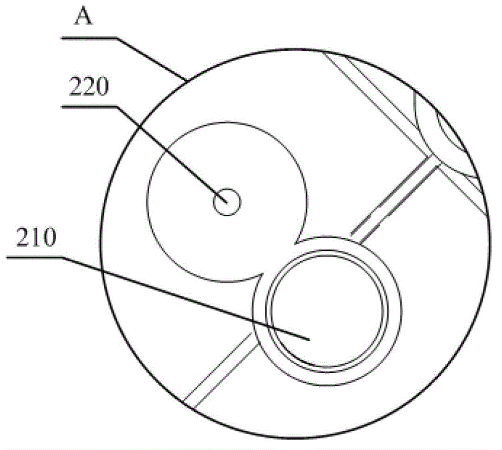
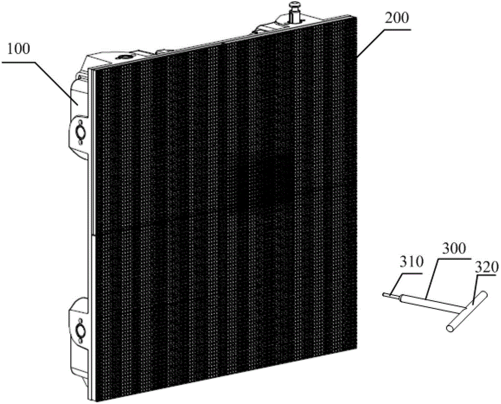
[0022] refer to Figure 1 to Figure 5 , figure 1 It is a schematic structural diagram of the assembly surface of the display module 200 of the LED display screen of the present invention; figure 2 for figure 1 The magnified image at A in the middle; image 3 It is a structural schematic diagram of the assembled and fixed state of the display module 200 and the box body 100 of the LED display screen of the present invention; Figure 4 It is a structural schematic diagram of the detached state of the display module 200 and the cabinet 100 of the LED display screen of the present invention; Figure 5 for Figure 4 Enlarged image at B.
[0023] In the embodiment o...
PUM
 Abstract
Description
Claims
Application Information
PatSnap Eureka turns technology decisions into work you can execute. Powered by our Innovation Knowledge Graph, it runs expert workflows across engineering, life sciences, materials and intellectual property. Get your review-ready output in minutes.


