
A Spectroscopic Monitoring Device Based on Multi-Channel Parallel Optical Signals

A monitoring device and optical signal technology, applied in the field of optical fiber communication, can solve the problems of inconsistent records, difficult inventory of network resources, brittle fiber texture, etc., and achieve the effects of high monitoring accuracy, easy implementation and low cost.

Active Publication Date: 2016-04-13
HUAZHONG UNIV OF SCI & TECH
View PDF8 Cites 0 Cited by
  • Summary
  • Abstract
  • Description
  • Claims
  • Application Information

AI Technical Summary

Problems solved by technology

Compared with the point-to-point (P2P) structure of traditional copper wires, the optical distribution network mostly adopts the point-to-multipoint (P2MP) topology structure, and there are more connection points in the network. Low, easy to break, so its connection is relatively difficult, and it causes the inconvenience of branching and coupling, and there are problems in reliability; at the same time, fiber resources become "black box" resources due to their passive characteristics , making it difficult to manage effectively, so the main problems we are currently facing are: the existing network resources are difficult to take inventory, the actual usage is inconsistent with the resource management system records, and the opening of new services needs to go through a complicated process, which cannot match the needs of fast service opening, etc.
[0004] However, whether it is the above solutions of Huawei or ZTE, they are all based on a variety of auxiliary equipment, such as handheld PDAs, optical fiber ID sensors, GIS systems and RFID tags, etc., and in the actual monitoring process However, considering the complexity of the application and the conditions in remote areas, it is often impossible to achieve a convenient and ready monitoring process

Method used


Image

  • A Spectroscopic Monitoring Device Based on Multi-Channel Parallel Optical Signals
  • A Spectroscopic Monitoring Device Based on Multi-Channel Parallel Optical Signals
  • A Spectroscopic Monitoring Device Based on Multi-Channel Parallel Optical Signals

Examples


Embodiment Construction

[0033] In order to make the object, technical solution and advantages of the present invention clearer, the present invention will be further described in detail below in conjunction with the accompanying drawings and embodiments. It should be understood that the specific embodiments described here are only used to explain the present invention, not to limit the present invention. In addition, the technical features involved in the various embodiments of the present invention described below can be combined with each other as long as they do not constitute a conflict with each other.

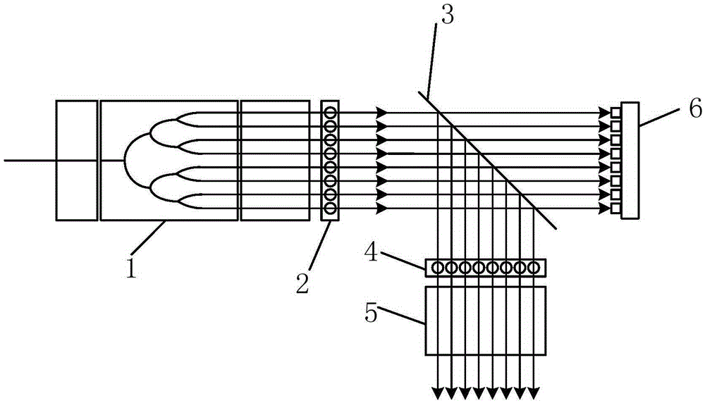
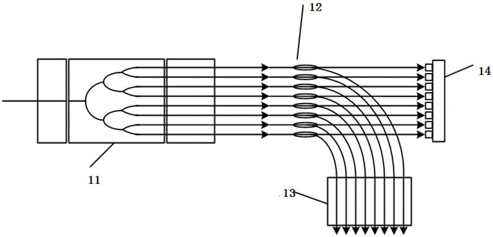
[0034] Aiming at the technical defects or improvement needs in the prior art, combined with the requirements for optical fiber transmission signal management in the optical fiber communication system, the present invention provides a spectroscopic monitoring device based on multi-channel parallel optical signals, which will be described in conjunction with the accompanying drawings below The spe...


PUM


Abstract

The invention discloses a light splitting monitoring device based on multi-channel parallel optical signals, which comprises an optical signal transmission module, a light splitting module, a coupling lens array, an optical signal receiving and transmitting module and an optical signal detecting unit, wherein the optical signal transmission module is used for transmitting parallel multi-channel optical signals and conveying the optical signals to the light splitting module after collimation processing is performed to the optical signals; the light splitting module performs light splitting to the optical signals, so that two kinds of parallel multi-channel optical signals conveyed in the different directions are acquired; one kind of the parallel optical signals is continuously transmitted to the optical signal detecting unit and state detection is carried out in the optical signal detecting unit; the other kind of parallel optical signals passes through the coupling lens array and the optical signal receiving and transmitting module in sequence, so that the normal communication process is continuously carried out. The invention further discloses other forms of light splitting monitoring devices. Through the light splitting monitoring device, the passive feature of a light path is not changed and the normal communication is guaranteed, and the monitoring of the multi-channel optical signals are smoothly realized at the same time, and the light splitting monitoring device has the characteristics of high monitoring precision, convenience for operation, wide application and the like.

Description

technical field [0001] The invention belongs to the technical field of optical fiber communication, and more specifically relates to a spectroscopic monitoring device based on multi-channel parallel optical signals. Background technique [0002] For the current fiber-to-the-home process, the proportion of investment in optical distribution network lines in fiber-to-the-home is increasing, accounting for about 60% of the total investment, and accounting for more than 90% of the initial construction costs. Therefore, the optical distribution network (ODN) has become one of the key links in promoting the construction of fiber-to-the-home (FTTH). Compared with the point-to-point (P2P) structure of traditional copper wires, the optical distribution network mostly adopts the point-to-multipoint (P2MP) topology structure, and there are more connection points in the network. Low, easy to break, so its connection is relatively difficult, and it causes the inconvenience of branching ...

Claims


Application Information

Patent Timeline
Patent Type & Authority Patents(China)
IPC IPC(8): H04B10/07H04Q11/00
Inventor 徐军蒋晶罗慕尧万助军
Owner HUAZHONG UNIV OF SCI & TECH
Learn More