Method of synchronizing in split torque continuously variable dual clutch transmission

A technology of transmission and stepless speed change, which is applied in the direction of fluid transmission, transmission, transmission control, etc., and can solve problems such as damage to synchronous devices

Inactive Publication Date: 2013-10-02
CATERPILLAR INC
View PDF1 Cites 8 Cited by
  • Summary
  • Abstract
  • Description
  • Claims
  • Application Information

AI Technical Summary

Problems solved by technology

If the relative velocity at the start of the synchronization process is too larg

Method used


Image

  • Method of synchronizing in split torque continuously variable dual clutch transmission
  • Method of synchronizing in split torque continuously variable dual clutch transmission
  • Method of synchronizing in split torque continuously variable dual clutch transmission

Examples


Embodiment Construction

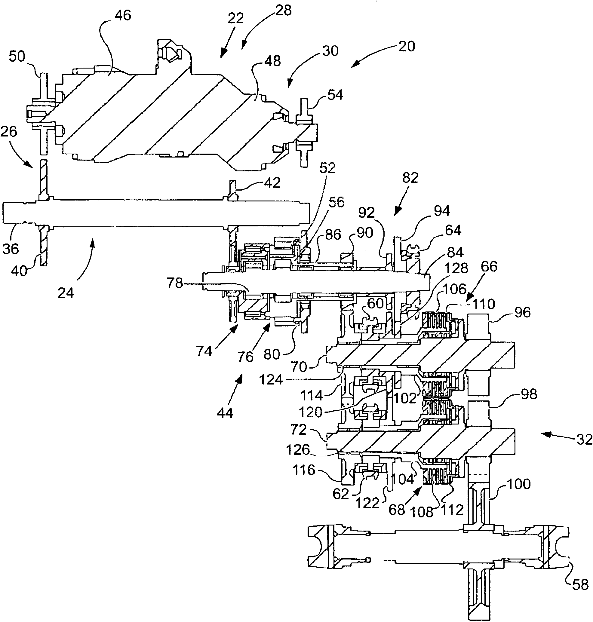
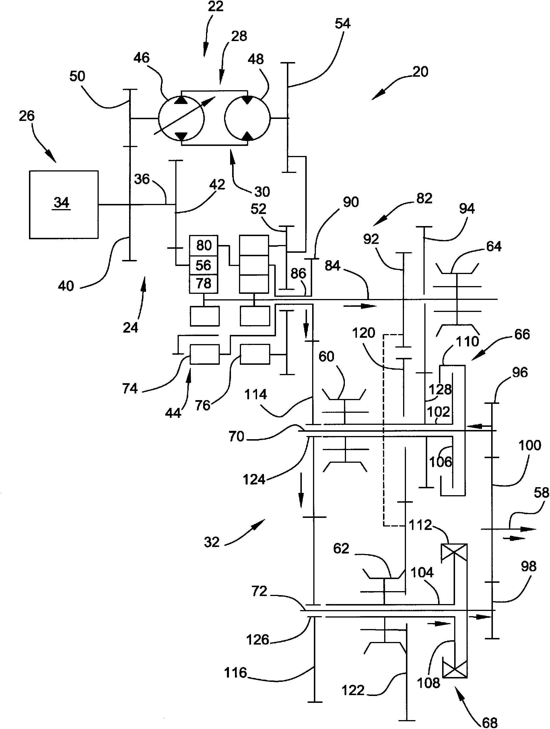
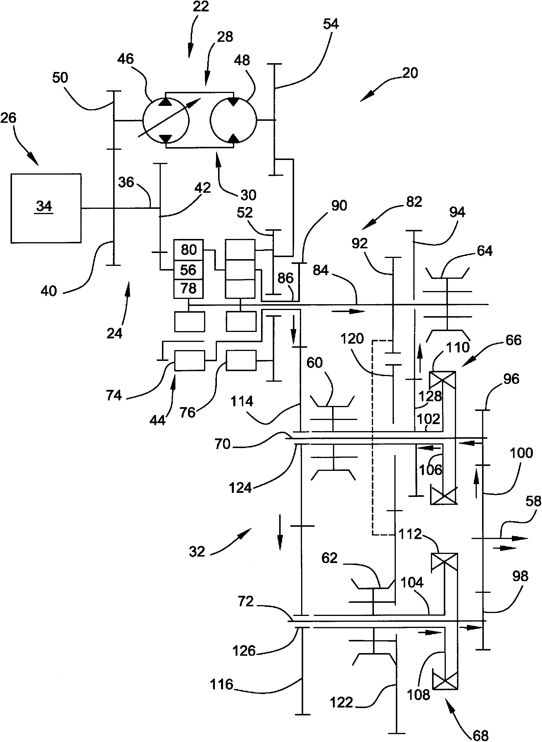
[0013] The invention relates to a method of synchronization in a split torque arrangement in a continuously variable transmission. The method described has general applicability to any machine using such an arrangement. For example, the term "machine" may refer to any machine that performs some type of operation related to an industry such as mining, construction, agriculture, transportation, or any other industry known in the art. By way of example only, a machine may be a vehicle, backhoe loader, road planer, wheel loader, soil compactor, feller buncher, forestry machine, conveyor, harvester, excavator, industrial loader , pincer loaders, material handlers, motor graders, pipelayers, road material remixers, skid steer loaders, skidders, telehandlers, tractors, bulldozers, tractor-scrapers or other paving or Underground mining equipment. Additionally, one or more instruments may be connected to the machine and may be driven by transmissions.

[0014] refer to figure 1 , s...


PUM


Abstract

A method including activating a first clutch assembly (66) to connect a first rotatable member (106) to a rotating final output member (58) until a shift trigger point is reached to provide a rotational speed to the first rotatable member (106) from the final output member (58). The first clutch assembly (66) is then deactivated. The second clutch assembly (68) that connected a synchronized second rotatable member (108) with the final output member (58) is then deactivated. A third synchronizer (64) engaged with the first rotatable member (106), and the first clutch assembly (66) is activated to connect the first rotatable member (106) to the final output member (58).

Description

technical field [0001] The present invention relates generally to a continuously variable transmission, and more particularly to a method of synchronizing components in a hydromechanical dual clutch transmission. Background technique [0002] Multi-stage hydromechanical transmissions are well known. Range changes are made by successively disengaging and engaging some of the synchronizers and clutch assemblies. A torque-split continuously variable transmission (CVT) may use an automatic dual clutch coupled to multiple synchronizers. For example, US Patent 7,530,913 to Fabry et al. discloses a multi-stage hydromechanical transmission comprising two clutch assemblies and three synchronizers. This patent is assigned to the assignee of the present invention. If the relative speed at the beginning of the synchronization process is too high, all synchronization devices are liable to be destroyed during the synchronization process. [0003] The proposed synchronization method in...

Claims


Application Information

Patent Timeline
IPC IPC(8): F16H61/04F16H47/04
CPCF16H47/02F16H47/04F16H61/0403F16H2037/0886F16H2061/283
Inventor K·莫洛尼
Owner CATERPILLAR INC
Why Eureka
Try Eureka