
Cervical posterior lateral mass screw fixation guide and screw fixation method

A technology of screw fixation and guide, which is applied in the fields of fixers, fastening devices, medical science, etc., can solve the problem that the screw screwing direction cannot be accurately controlled, and achieve the effect of reducing surgical risk, simple positioning method, and firm screw fixation

Inactive Publication Date: 2015-08-19
胡亚兰
View PDF7 Cites 0 Cited by
  • Summary
  • Abstract
  • Description
  • Claims
  • Application Information

AI Technical Summary

Problems solved by technology

[0003] One of the purposes of the present invention is to provide a guider for cervical posterior lateral mass screw fixation, so as to solve the problem that the screw screwing direction cannot be accurately controlled

Method used


Image

  • Cervical posterior lateral mass screw fixation guide and screw fixation method
  • Cervical posterior lateral mass screw fixation guide and screw fixation method
  • Cervical posterior lateral mass screw fixation guide and screw fixation method

Examples


Embodiment 1

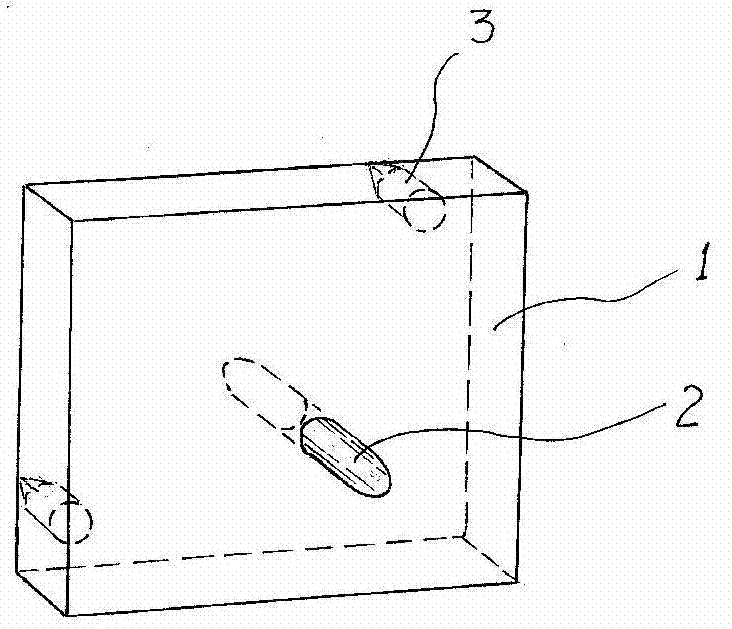
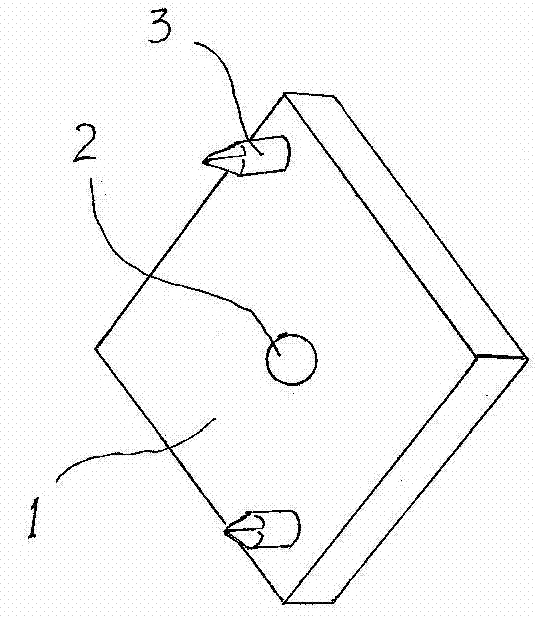
[0020] Embodiment 1: The screw fixation guide for the posterior lateral mass of the cervical spine of the present invention includes a left guide and a right guide, and the left guide and the right guide have left-right symmetrical structures.

[0021] figure 2 , image 3 It is a schematic diagram of the structure of the front and back of the left guide. The specific structure is to make a square positioning plate 1 with a side length of 1.18-1.22cm and a thickness of 1.48-1.52mm. To the through hole 2 passing through the board surface, the diameter of the through hole is 1.0-1.3mm, and the direction of the through hole is to pass through the board surface obliquely from the direction of the lower right corner of the front of the positioning board 1 to the direction of the upper left corner of the back, and the direction of the through hole is The included angle between the axis line and the projection line of the axis line on the positioning plate 1 is 20°. The center poin...

Embodiment 2

[0022] Embodiment 2: The screw fixation method of the cervical posterior lateral mass of the present invention comprises the following steps:

[0023] a. Align the left side and the bottom edge of the positioning plate 1 of the left guide with the nearly right-angled protruding edge on the left lateral mass of the posterior cervical spine, so that the positioning plate 1 basically covers the left lateral mass of the posterior cervical spine top surface.

[0024] b. Hammer the surface of the positioning plate 1 of the left guide, and nail the positioning nail 3 on the positioning plate 1 into the bone of the posterior lateral mass of the cervical spine.

[0025] c. Insert a drill bit with a diameter of 0.8-0.9 mm into the through hole 2 on the left guide positioning plate 1, and drill in the bone of the posterior cervical vertebra along the axis of the through hole 2 Hole operation, the drilling depth does not exceed 3mm.

[0026] d. Repeat steps a-c, and use the right guide ...


PUM


Abstract

The invention relates to a posterior cervical vertebra side block screw fixing guide device and a screw fixing method. According to the structure of the screw fixing guide device, the middle of a place face of a square positioning plate with the edge of 1.18-1.22cm is provided with a through hole which penetrates through the right lower corner of the front face of the positioning plate to the left upper corner of the back side of the positioning plate in an inclined mode. The included angle between the axis of the through hole and a projection line, on the positioning plate, of the axis is 20 degrees. The position, on the left lower corner, of the plate face on the back side of the positioning plate and the position, on the right upper corner, of the place face of the back side of the positioning plate are respectively provided with a positioning nail extending backwards. By means of the guide device, the drilling direction of a drill is determined. By means of the operation procedures that holes are firstly drilled, and then screws are screwed, an original operation mode that the screws are screwed for fixing a steel plate according to experience is changed, the correctness of the screwing direction of the screws is guaranteed, firm fixing of the screws is guaranteed, and nerves and vessels on the two sides of the cervical vertebra of a patient are not harmed. Therefore, safety of posterior cervical vertebra side block fixation is greatly improved, and operation risks of posterior cervical vertebra laminectomy are reduced.

Description

technical field [0001] The invention relates to a surgical instrument, in particular to a screw fixation guider and a screw fixation method for the posterior lateral mass of the cervical spine. Background technique [0002] Currently, in clinical practice, posterior cervical laminectomy is often required for patients with neck diseases. During the operation, in order to maintain the stability of the cervical spine, the posterior cervical mass is usually first fixed with a steel plate, and there are strict requirements on the angle at which the screws used to fix the plate pass through the posterior cervical mass. The physiological structure of the posterior cervical spine is as follows: figure 1 As shown in (a), the fixation angle of the screw on the posterior lateral mass of the cervical spine starts from the needle entry point on the lateral mass on both sides, and it should deviate 30° to the outside of the cervical spine, as shown in figure 1 As shown in (b), it should...

Claims


Application Information

Patent Timeline
Patent Type & Authority Patents(China)
IPC IPC(8): A61B17/90A61B17/86
Inventor 胡亚兰李楠郭明珂田淑娟霍江涛马广骏孟宪涛郑永波谭立国李涛
Owner 胡亚兰
Learn More