Adhering self-elevating-type tower crane for hoisting wind power equipment

A wind power equipment, self-elevating technology, applied in the direction of cranes, etc., can solve the problems of the difficulty of entering large lifting equipment, the high cost of large cranes, the limitation of large lifting equipment, etc., to achieve light weight, low self-height, and less restrictive conditions. Effect

Active Publication Date: 2013-10-09
SINOHYDRO BEREAU 10 CO LTD
View PDF9 Cites 9 Cited by
  • Summary
  • Abstract
  • Description
  • Claims
  • Application Information

AI Technical Summary

Problems solved by technology

Large-scale cranes are expensive (about 100,000 yuan per ton), limited in resources, and limited in scope of use, making it difficult for general enterprises to equip them
At present, most of the single-unit capacity of wind power generation equipment on land is below 1.5MW, mainly due to the limitation of hoisting resources. Most of them are built on the Gobi Desert, and there are few areas in mountain passes and valleys. The main reason is that it is difficult for large-scale hoisting equipment to enter the site. Other power generation equipment in China is making great strides towards the world, but there are few wind power generation equipment, which is also the reason why the corresponding large-scale lifting equipment is restricted.

Method used


Image

  • Adhering self-elevating-type tower crane for hoisting wind power equipment
  • Adhering self-elevating-type tower crane for hoisting wind power equipment
  • Adhering self-elevating-type tower crane for hoisting wind power equipment

Examples


Embodiment Construction

[0023] Below in conjunction with accompanying drawing, the present invention is described in further detail:

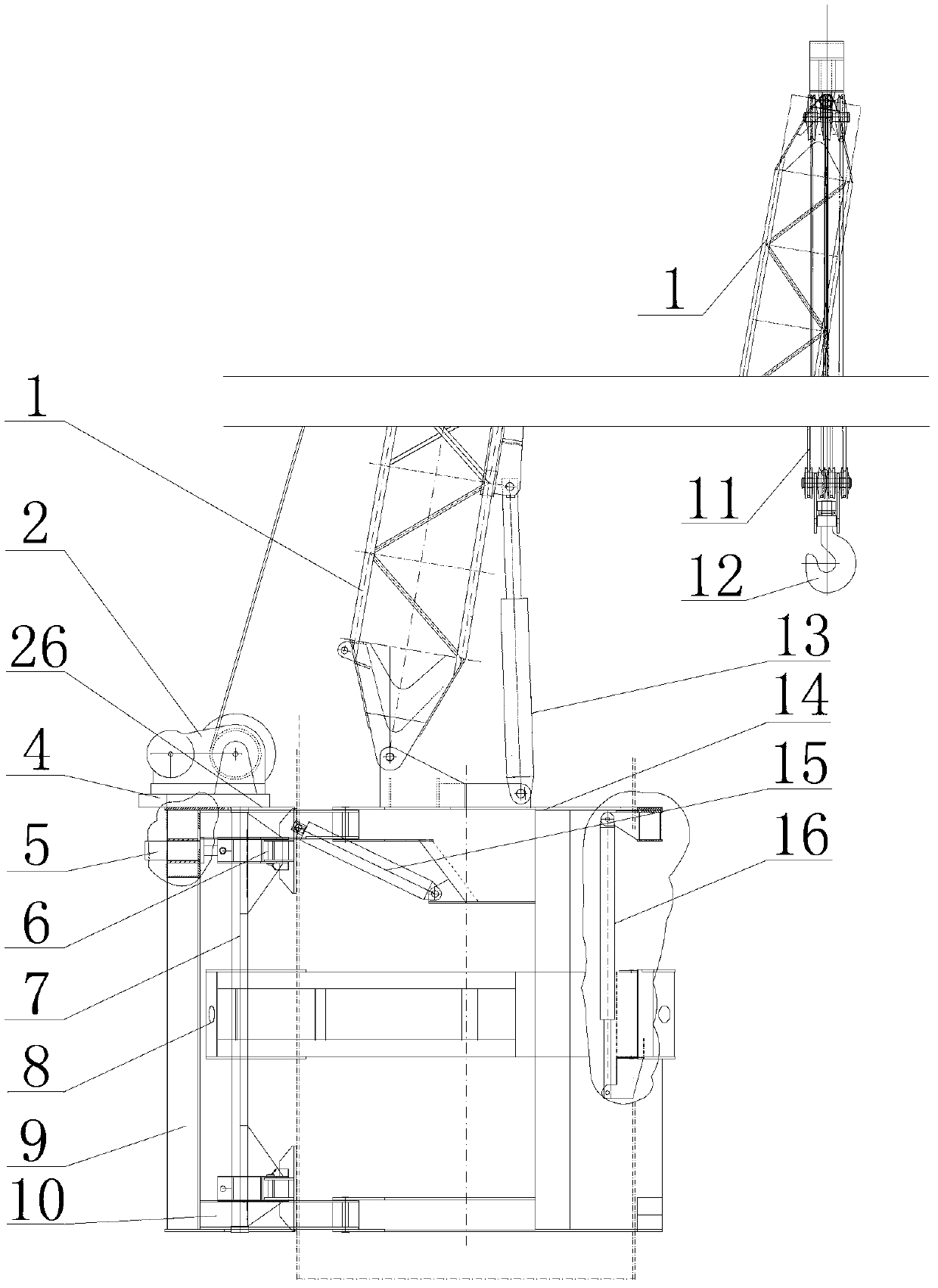
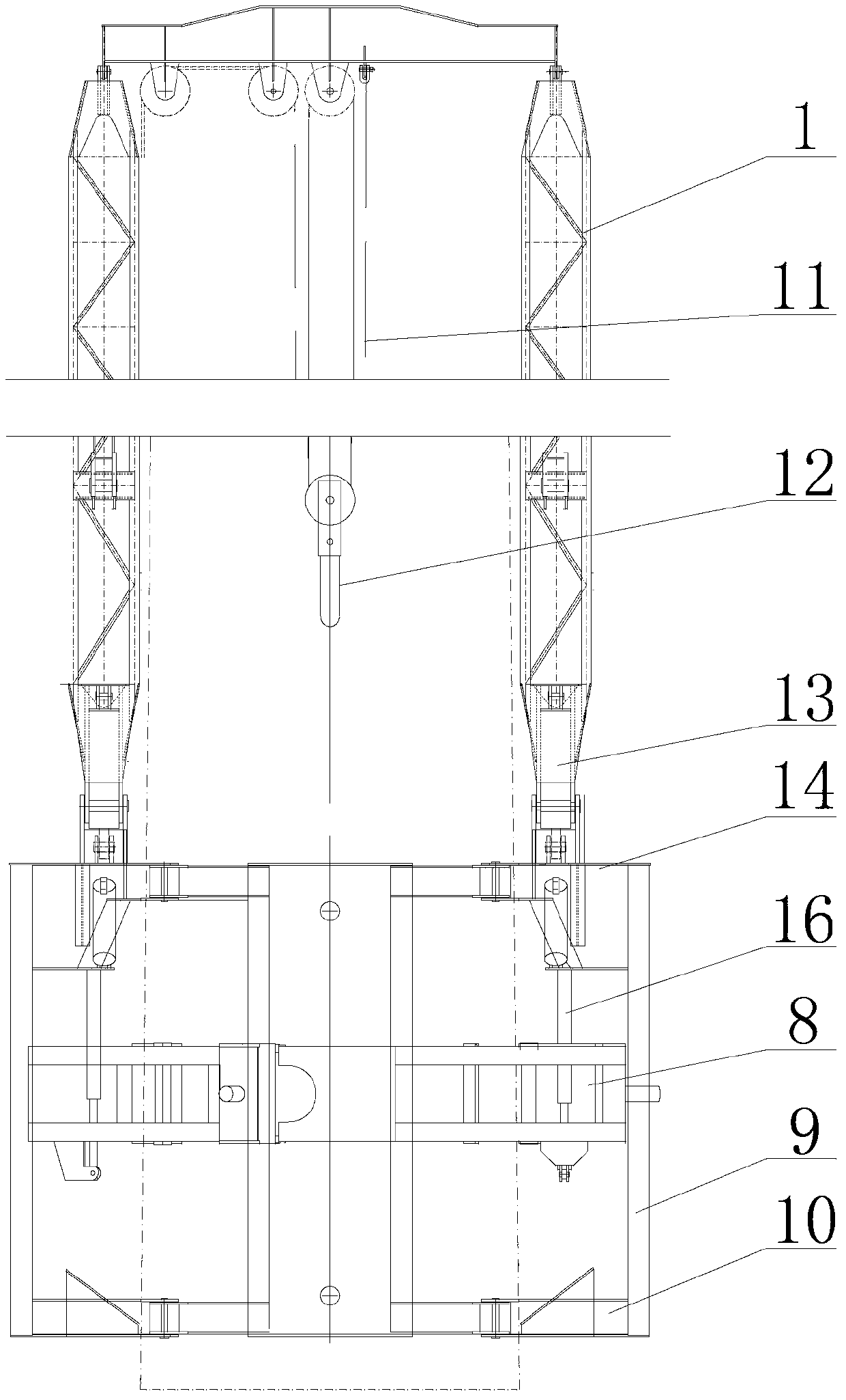
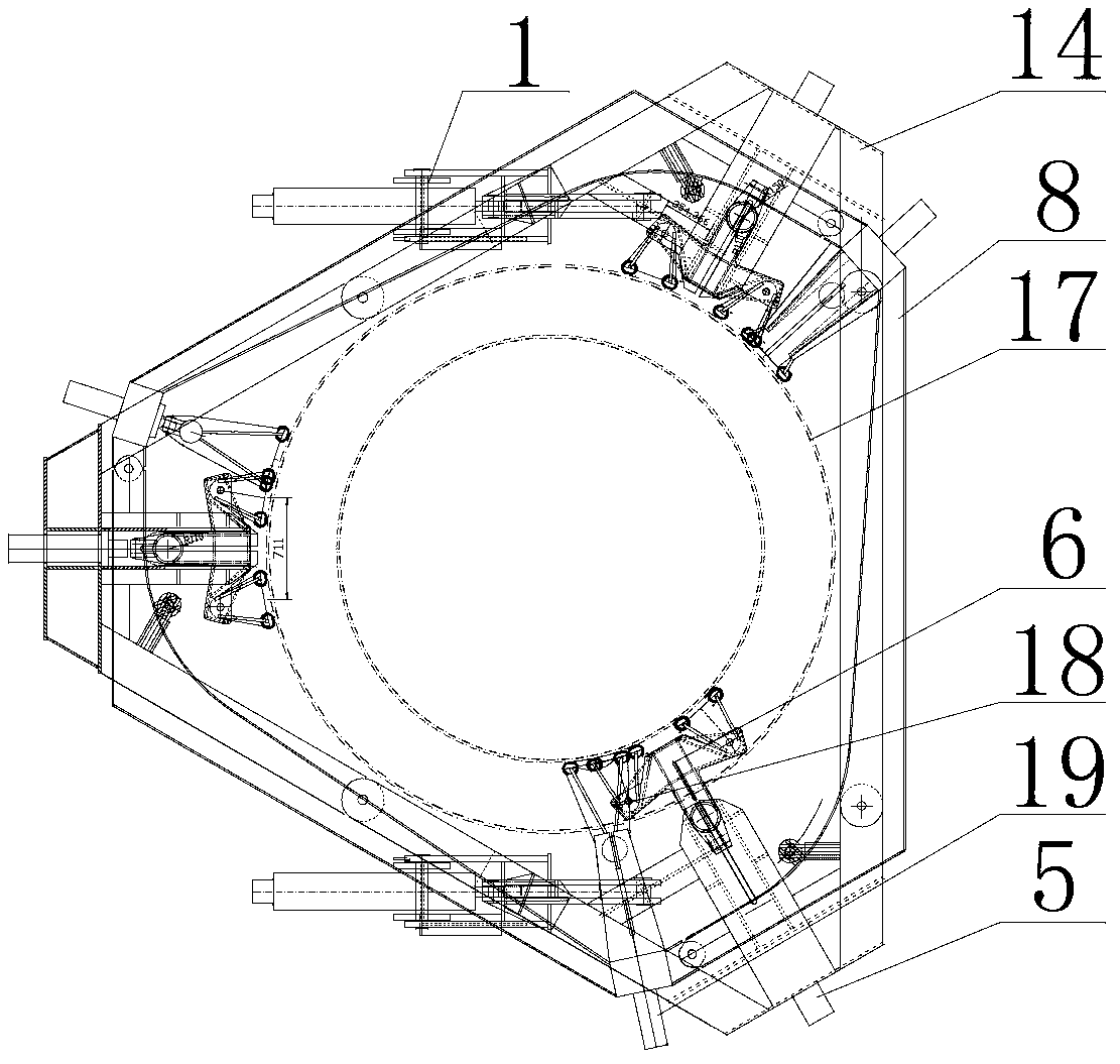
[0024] Such as figure 1 , figure 2 with image 3 As shown, the self-elevating tower crane attached to the wind power equipment hoisting of the present invention includes a lifting device, a main frame 14, a main holding cylinder 5, a main holding arm 6, an auxiliary frame 8, an auxiliary holding cylinder 19, and an auxiliary holding arm 18 And lifting oil cylinder 16, the axial direction of lifting oil cylinder 16 is vertical direction, and the oil cylinder base of lifting oil cylinder 16 and piston rod are connected with main frame 14 and auxiliary frame 8 respectively, and the oil cylinder seat of main holding oil cylinder 5 is installed on main frame 14 Above, the piston rod of the main holding cylinder 5 is connected to the main holding arm 6, the main holding arm 6 is placed inside the main frame 4, the cylinder seat of the auxiliary holding cylinder 19 is ins...


PUM


Abstract

The invention discloses an adhering self-elevating-type tower crane for hoisting wind power equipment. The adhering self-elevating-type tower crane of the wind power equipment comprises an elevating device, a main framework, a main clasping oil cylinder, a main clasping arm, an auxiliary framework, an auxiliary clasping oil cylinder, an auxiliary clasping arm and an elevating oil cylinder; the axial direction of the elevating oil cylinder is the vertical direction; an oil cylinder seat and a piston rod of the elevating oil cylinder are respectively connected with the main framework and the auxiliary framework; the oil cylinder seat of the main clasping oil cylinder is installed on the main framework; a piston rod of the main clasping oil cylinder is connected with the main clasping arm; the main clasping arm is arranged on the inner side of the main framework; an oil cylinder seat of the auxiliary clasping oil cylinder is installed on the auxiliary framework; a piston rod of the auxiliary clasping oil cylinder is connected with the auxiliary clasping arm; the auxiliary clasping arm is arranged on the inner side of the auxiliary framework; the inner side of the main clasping arm and the inner side of the auxiliary clasping arm are both used for clasping a fan tower section; and the elevating device is installed on the main framework. The tower crane is adhered to the fan tower section repeatedly through the main framework and the auxiliary framework in application, so that the whole tower crane climbs to the required height, and is elevated; the adhering self-elevating-type tower crane for hoisting the wind power equipment has the advantages of light weight, low manufacture cost and less limited conditions.

Description

technical field [0001] The invention relates to a wind power equipment hoisting tower crane, in particular to a wind power equipment hoisting attached self-elevating tower crane with light weight, low cost and few restricted conditions. Background technique [0002] At present, the installation of large-scale wind power generation equipment in China and the world is completed with large truck cranes or crawler cranes. Since the 1.5MW wind turbine cabin equipment weighs more than 60 tons and is installed at a height of about 70 meters, a 500-ton truck crane or a 400-ton crawler crane is required for hoisting. , 3MW, 5MW, and 6MW wind power generation requires more than 1,000 tons of cranes to hoist, and the offshore 5MW wind turbine installation of the "Super Project" used a 3,000-ton crane. Large-scale cranes are expensive (about 100,000 yuan per ton), limited in resources, and limited in scope of use, making it difficult for general enterprises to equip them. At present, m...

Claims


Application Information

Patent Timeline
Patent Type & Authority Applications(China)
IPC IPC(8): B66C23/28B66C23/80B66C23/82
Inventor 赖德元
Owner SINOHYDRO BEREAU 10 CO LTD
Why Eureka
Try Eureka