Bridge crane main beam

An overhead crane and main beam technology, which is applied in the directions of load hanging components, transportation and packaging, support structures, etc., can solve the problems of limited choice of main beams, consuming materials and power, increasing the weight of main beams, etc., to save energy and raw materials. , easy maintenance, and the effect of improving the carrying capacity of the crane

Inactive Publication Date: 2014-10-08
何书贵
View PDF5 Cites 0 Cited by
  • Summary
  • Abstract
  • Description
  • Claims
  • Application Information

AI Technical Summary

Problems solved by technology

[0002] The main girders of bridge cranes in the prior art are all welded with I-shaped steel or steel plates to form a box structure, and the strength and rigidity of the crane are mainly determined by the section size of the main girder and the rigidity of the truss. One is to increase the rigidity of the truss, and the other is to increase the specification and model of the main beam, which greatly increases the weight of the main beam and consumes materials and power
Generally speaking, the reinforcement of the crane truss is relatively easy, while the selection of the main beam is relatively limited

Method used


Image

  • Bridge crane main beam
  • Bridge crane main beam
  • Bridge crane main beam

Examples


Embodiment 1

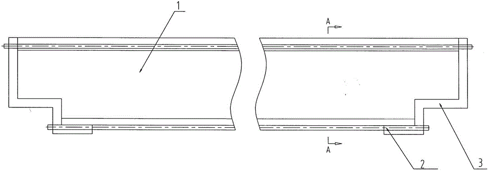
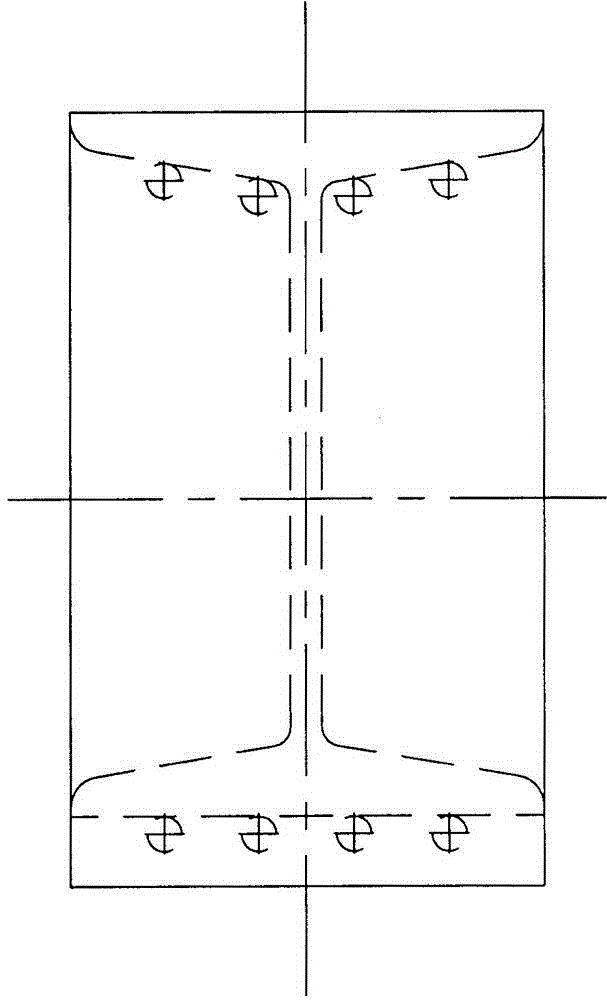
[0018] like figure 1 , 2 , 3, the main girder of the bridge crane of the present invention includes the I-beams that are respectively fixedly connected with the positioning plate 3 as the two ends of the main girder 1, and the bottom surface of the I-beam and the I-beam The bottom surface of the upper wing plate of the steel beam is arranged longitudinally side by side with prestressed steel wire ropes 4, and the horizontal arrangement of the said prestressed steel wire ropes 4 is symmetrically arranged according to the center line of the beam body, and is arranged at intervals along the length direction of the main beam 1 beam body. The prestressed steel wire rope is positioned by the plate and the sheath; the prestressed steel wire rope is covered with a wrapping layer made of stainless steel material, and the wrapping layer is coated with anti-rust grease; the two ends of the main beam 1 are fixed with positioning plate 3, the two ends of the prestressed steel wire rope 4 ...

Embodiment 2

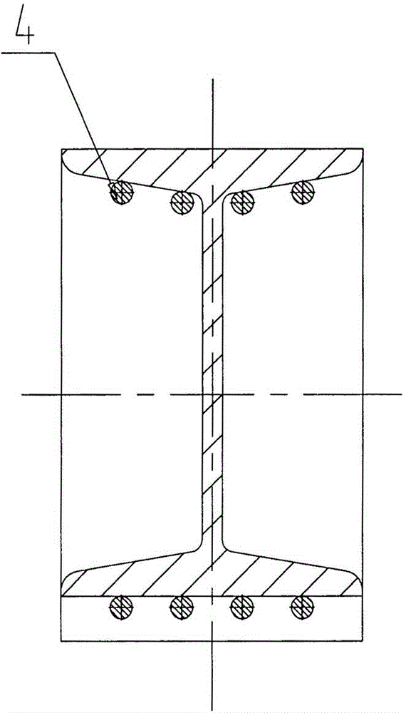
[0021] like Figure 4 As mentioned above, the difference between this embodiment and Embodiment 1 is that the main girder of the bridge crane of the present invention is composed of a rectangular box girder with positioning plates 3 fixedly fixed at both ends, and the rectangular box girder The bottom surface and the bottom surface of the rectangular box girder top plate are provided with prestressed steel wire ropes 4 arranged side by side longitudinally.

[0022] The specifications, quantity and prestress size of the prestressed steel wire rope among the present invention, according to the crane specification, select the bearing strength value that design will increase, select the specification and root number of the steel wire rope and I-beam or rectangular box by the size of the strength value beam specification. The trolley track is set on the main girder. When the crane lifts heavy objects, the steel wire rope bears the maximum tension, thereby greatly reducing the load...


PUM


Abstract

The invention discloses a bridge crane main beam. The bridge crane main beam comprises an I-shaped steel beam or a rectangular box beam which is used as a main beam and is provided with a positioning plate arranged at each of two ends. The bridge crane main beam is characterized in that the bottom surface of the I-shaped steel beam and the bottom surface of an upper wing plate of the I-shaped steel beam or the bottom surface of the rectangular box beam and the bottom surface of a top plate of the rectangular box beam are provided with at least two prestress steel wire ropes in a longitudinal and side-by-side manner; one ends of the prestress steel wire ropes are fixed on the positioning plates which are fixedly connected with the corresponding end of the main beam, and the other ends of the prestress steel wire ropes are arranged in a locking device arranged on the positioning plate penetrating through the corresponding end of the main beam. Compared with the prior art, the bridge crane main beam provided by the invention has the characteristics that the application amount of a material is greatly reduced, the structure is light, economic and reduced, the production efficiency is improved, the self height is small, the weight is light, the installation is simple and convenient, the power of a complete machine is small, the using cost is low, the maintenance is simple and convenient, the soil construction requirement is low and the like; an energy source raw material is saved, and a new way for module production is opened up.

Description

technical field [0001] The invention relates to a main girder of an overhead crane. Background technique [0002] The main girders of bridge cranes in the prior art are all welded with I-shaped steel or steel plates to form a box structure, and the strength and rigidity of the crane are mainly determined by the section size of the main girder and the rigidity of the truss. One is to increase the rigidity of the truss, and the other is to increase the specification and model of the main beam, which greatly increases the weight of the main beam and consumes materials and power. Generally speaking, the reinforcement of the crane truss is relatively easy, while the selection of the main beam is relatively limited. How to greatly improve the strength of the crane beam without increasing the beam weight is a long-standing technical problem. Contents of the invention [0003] The object of the present invention is to provide a bridge crane main girder aiming at the shortcomings...

Claims


Application Information

Patent Timeline
Patent Type & Authority Applications(China)
IPC IPC(8): B66C6/00
Inventor 何书贵
Owner 何书贵
Why Eureka
Try Eureka