Friction parameter identification method for aerial remote-sensing inertial stabilization platform

An inertial stable platform and aviation remote sensing technology, applied in navigation, instrumentation, adaptive control and other directions through speed/acceleration measurement, can solve problems such as difficult to use and inconvenient maintenance, and achieve accurate friction model, accurate friction characteristics, high Effect of Accuracy Friction Torque Compensation

Inactive Publication Date: 2013-10-09
BEIHANG UNIV
View PDF6 Cites 33 Cited by
  • Summary
  • Abstract
  • Description
  • Claims
  • Application Information

AI Technical Summary

Problems solved by technology

However, purely mechanical design methods are often restricted by conditions such as processing technology level, material level, and research funding, and are not easy to maintain, so that they are difficult to us

Method used


Image

  • Friction parameter identification method for aerial remote-sensing inertial stabilization platform
  • Friction parameter identification method for aerial remote-sensing inertial stabilization platform
  • Friction parameter identification method for aerial remote-sensing inertial stabilization platform

Examples


Embodiment Construction

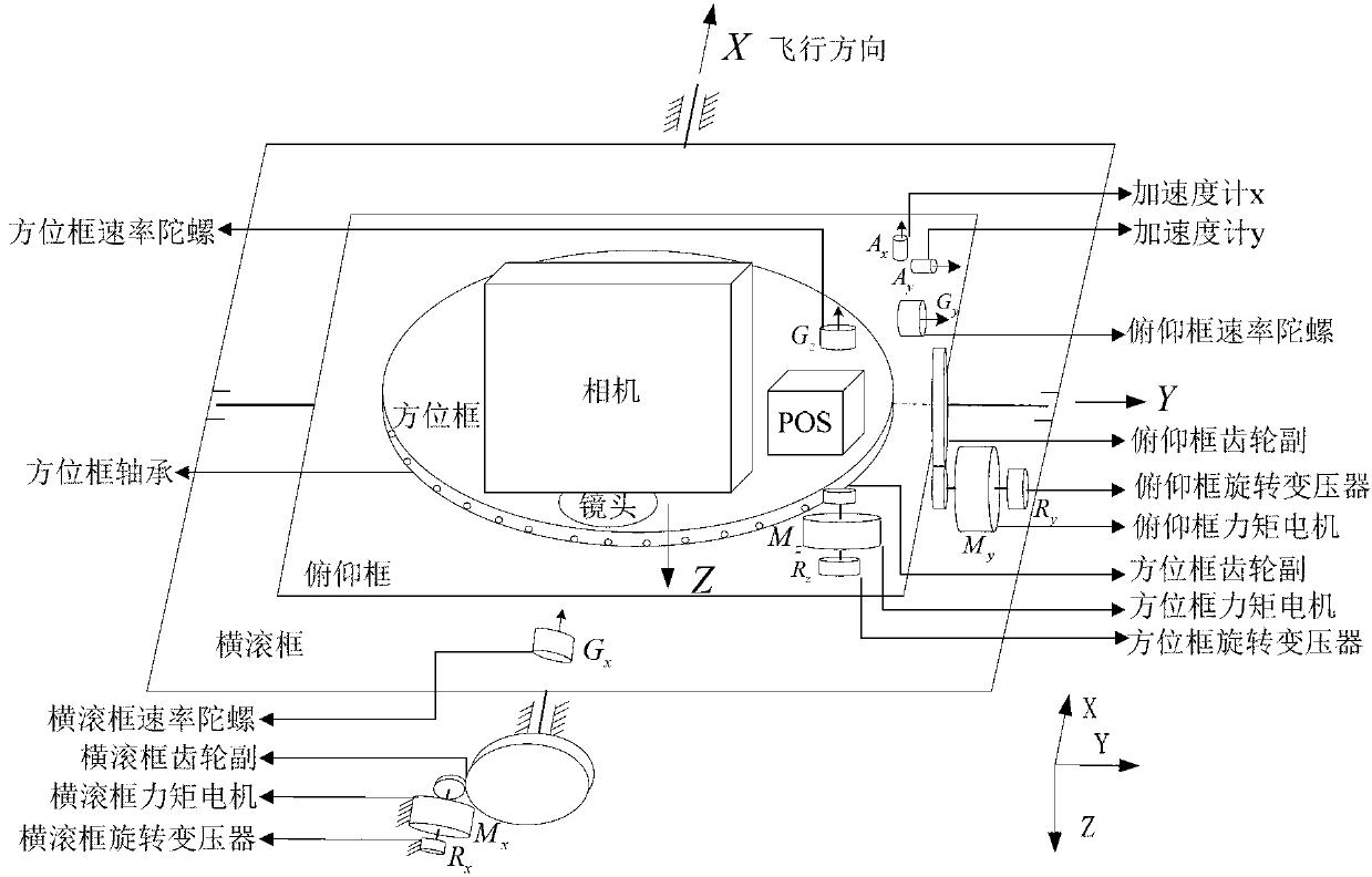
[0020] Such as figure 2 Shown is a schematic diagram of the structure of the three-axis inertial stabilization platform for aerial remote sensing. From the outside to the inside of the platform, there are roll frame, pitch frame and azimuth frame respectively. The rotation axis of the roll frame is along the flight direction, the rotation axis of the pitch frame is along the flight span direction, and the rotation axis of the azimuth frame is vertically downward, M x , M y , M z It is three torque motors, which respectively drive the rotation of the roll frame, the rotation of the pitch frame, and the rotation of the azimuth frame; G x ,G y ,G z is the rate gyroscope installed on each frame, sensitive to the rotational angular velocity of the three frames relative to the inertial space, A x , A y is the accelerometer installed on the pitch frame, where A x The sensitive axis of A is coincident with the rotation axis of the roll frame, A y The sensitive axis coincides ...


PUM


Abstract

The invention relates to a friction parameter identification method for an aerial remote-sensing inertial stabilization platform. The friction parameter identification method comprises the following steps of: establishing a LuGre friction model of the inertial stabilization platform based on the analysis of sinusoidal response curves of systems; and obtaining parameters of the LuGre friction model by respectively designing parameter identification schemes to three frame systems of the inertial stabilization platform and utilizing a two-step-identified and dynamic-parameter-optimized friction parameter identification method. According to the friction parameter identification method, the parameters of the LuGre friction model can be accurately obtained, the friction moment compensation can be realized, and the control precision and the stabilization precision of the systems of the inertial stabilization platform can be improved; the friction parameter identification method can be widely applied to the systems of various remote-sensing inertial stabilization platforms.

Description

technical field [0001] The invention relates to a friction parameter identification method of an aviation remote sensing inertial stabilization platform. Background technique [0002] The aerial remote sensing system has unique advantages in many aspects such as mobility, real-time performance, repeatable observation, replaceability of remote sensing equipment, ability to obtain high-resolution remote sensing data, economic cost, and stereoscopic observation. Therefore, in western developed countries, more than 65% of the high-resolution spatial data used for urban planning and basic map mapping are guaranteed by aerial remote sensing systems. High-resolution earth observation is an important direction for the development of aerial remote sensing systems. However, due to the influence of atmospheric turbulence and the factors of the carrier aircraft, the body of the carrier aircraft cannot be kept stable, causing the imaging load installed on the carrier aircraft to shake, a...

Claims


Application Information

Patent Timeline
IPC IPC(8): G01C21/18G05B13/04
Inventor 周向阳宫国浩刘炜房建成赵强李永
Owner BEIHANG UNIV
Why Eureka
Try Eureka