Micro-vibration vibration isolator damping parameter and rigidity parameter measuring device

A technology of micro-vibration isolators and damping parameters, which is used in measuring devices, testing of machine/structural components, instruments, etc. to achieve stable and reliable performance, wide application range and convenient use.

Inactive Publication Date: 2013-10-09
BEIHANG UNIV
3 Cites 15 Cited by

AI-Extracted Technical Summary

Problems solved by technology

[0006] It can be seen that these methods are not suitable for the measurement of damping parameters and stiffness parameters of micro-vibration isol...

Abstract

The invention discloses a micro-vibration vibration isolator damping parameter and rigidity parameter measuring device. The micro-vibration vibration isolator damping parameter and rigidity parameter measuring device comprises a rigidity fixed platform, an exciter, a micro-vibration vibration isolator, a test device and a control device. The two ends of the micro-vibration vibration isolator are connected with a strength bearing tool and the exciter respectively so that the micro-vibration vibration isolator and the exciter can be fixed on the rigidity fixed platform. The rear end of the micro-vibration vibration isolator is provided with a first acceleration sensor and a third acceleration sensor, the front end of the micro-vibration vibration isolator is provided with a second acceleration sensor, and four force sensors are fixed on the front end face of the micro-vibration vibration isolator. The control device is used for controlling the shock excitation action of the exciter on the micro-vibration vibration isolator and for controlling the excitation displacement amplitude of the exciter through a measurement signal of the first acceleration sensor. The test device is used for conducting calculation according to a measurement signal of the second acceleration sensor, a measurement signal of the third acceleration sensor and measurement signals of the four force sensors under different types of excitation displacement amplitudes of the exciter to obtain a damping coefficient of the micro-vibration vibration isolator and a rigidity parameter of the micro-vibration vibration isolator. The micro-vibration vibration isolator damping parameter and rigidity parameter measuring device has the advantages of being stable and reliable in performance and small in error of test data.

Application Domain

Technology Topic

Four-forceTest facility +6

Image

  • Micro-vibration vibration isolator damping parameter and rigidity parameter measuring device
  • Micro-vibration vibration isolator damping parameter and rigidity parameter measuring device
  • Micro-vibration vibration isolator damping parameter and rigidity parameter measuring device

Examples

  • Experimental program(1)

Example Embodiment

[0025] The present invention will be further described in detail below in conjunction with the accompanying drawings.
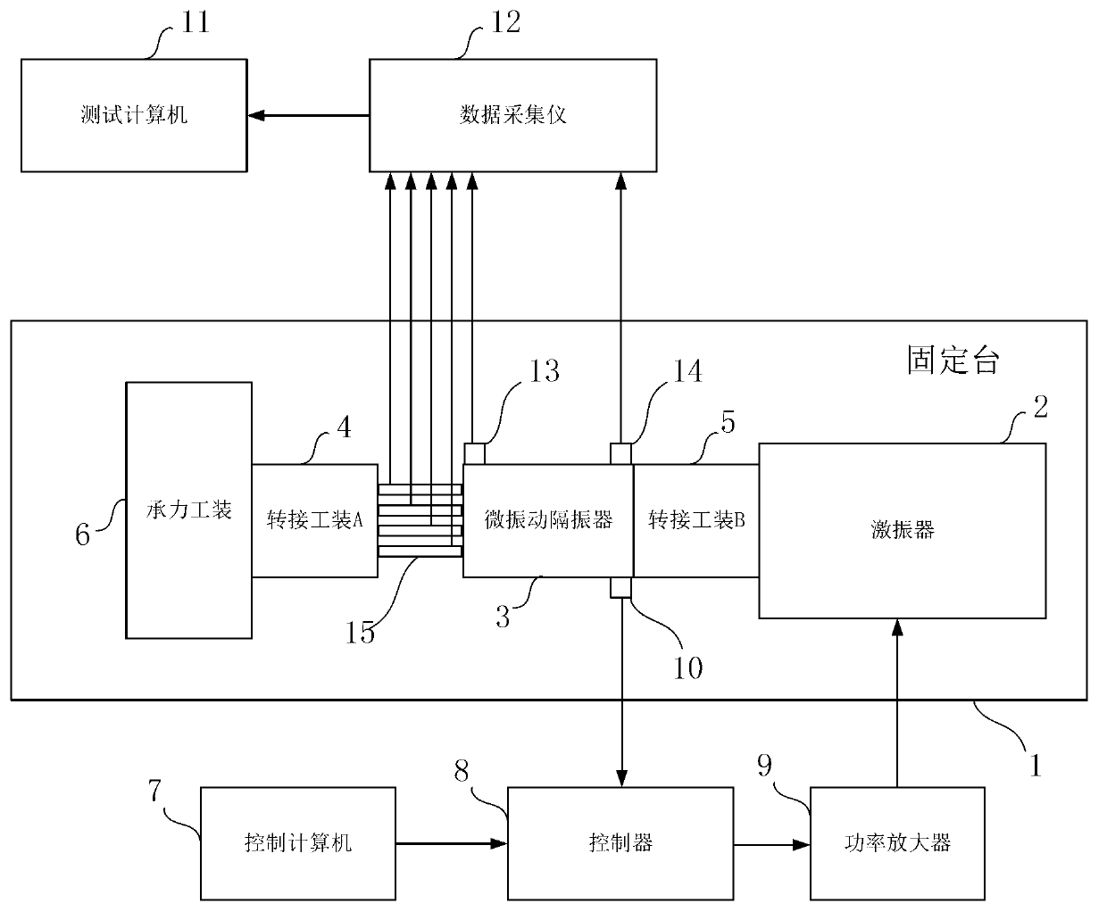
[0026] A device for measuring damping parameters and stiffness parameters of a micro-vibration isolator, including a rigid fixed table 1, a vibration exciter 2, a micro-vibration isolator 3, control equipment and test equipment, such as figure 1 Shown
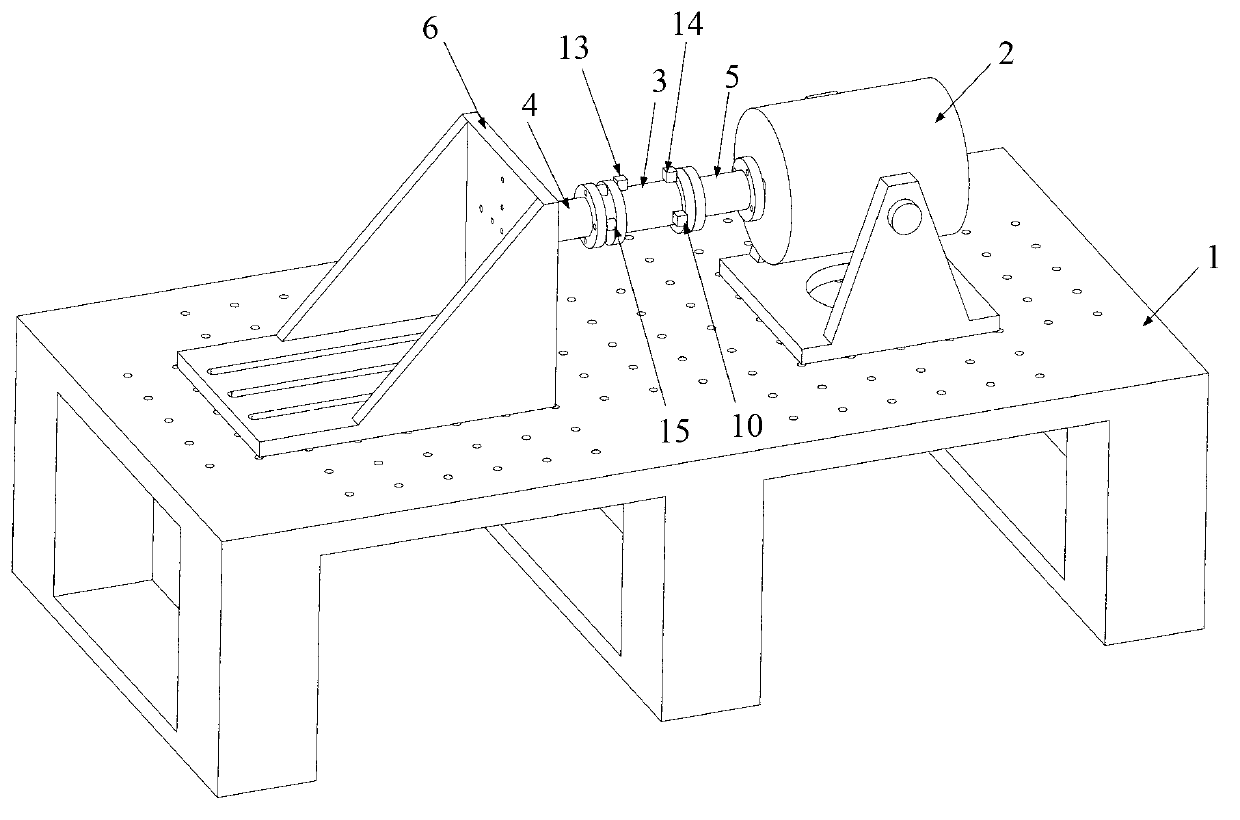
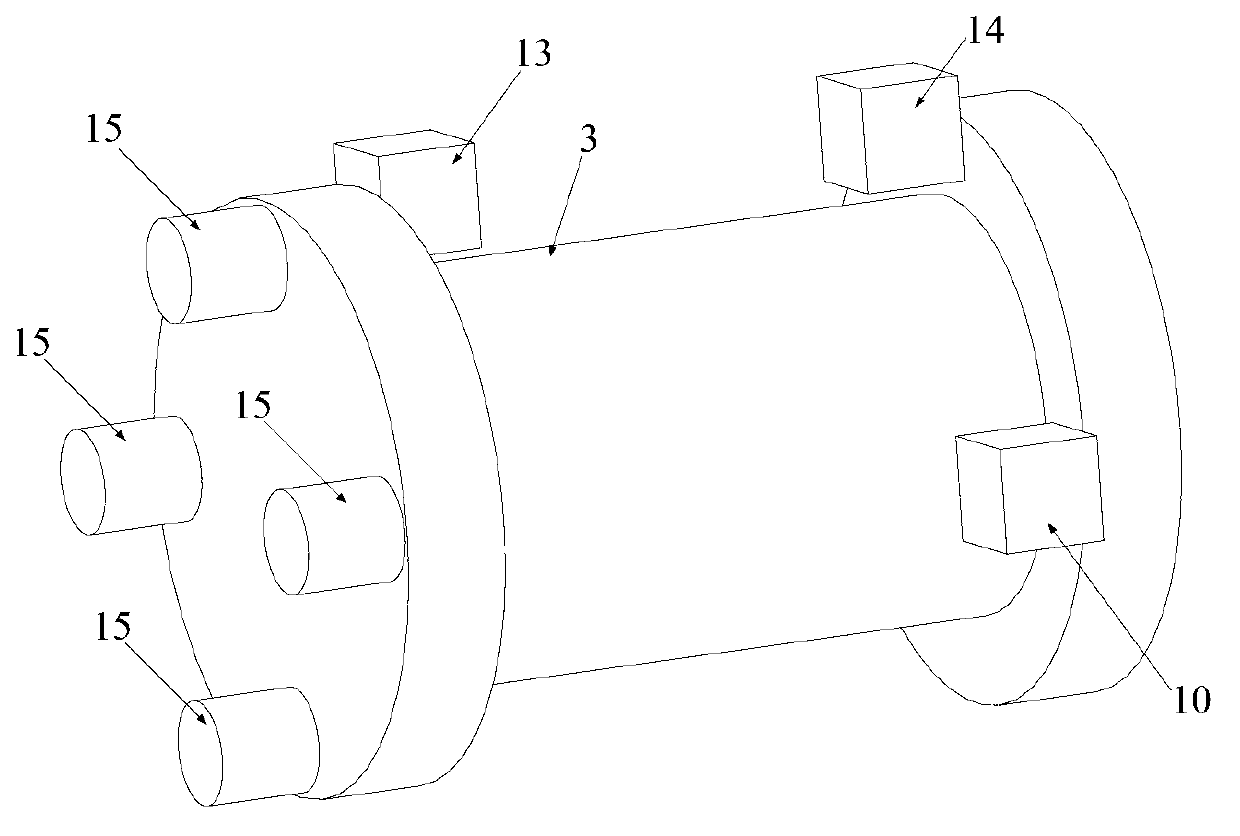
[0027] The upper surface of the rigid fixed platform 1 is horizontally arranged for installing the vibration exciter 2 and the micro-vibration isolator 3. The micro-vibration isolator 3 has a cylindrical structure, and the front and rear ends are respectively connected to the load-bearing tool 6 and the vibration exciter 2 through the column-shaped adapter tool A4 and the column-shaped adapter tool B5, such as figure 2 Shown; Among them, the exciter 2 is fixedly installed on the rigid fixed platform 1 through the exciter 2 bracket. The load-bearing tooling 6 is composed of a bottom plate, two side plates, and a connecting plate; the bottom plate is fixedly connected to the rigid fixing table 1; the connecting plate is perpendicular to the bottom plate as a connecting surface for fixed connection with the adapter tool A4; the bottom plate and the two connecting plates The sides are respectively connected by a side plate to realize the reinforcement of the entire load-bearing tooling 6. After the above connection, it is necessary to ensure that the exciter 2 and the micro-vibration isolator 3 are coaxial, and the axes of the exciter 2 and the micro-vibration isolator 3 are parallel to the rigid fixed platform 1.
[0028] The control device includes a control computer 7, a controller 8, a power amplifier 9 and a first acceleration sensor 10; the control computer 7 is connected to the controller 8; the controller 8 is connected to the power amplifier 9; the power amplifier 9 is connected to the vibration exciter 2 ; The first acceleration sensor 10 is fixedly installed at the rear end of the outer wall of the micro-vibration isolator and connected to the controller 8; wherein the control computer 7 is used to send a control signal C to the controller 8 1 , The controller 8 according to the control signal C 1 Output the excitation signal to the power amplifier 9; after the excitation signal is power-amplified by the power amplifier 9, it is transmitted to the vibration exciter 2, and the vibration exciter is controlled to excite the micro-vibration isolator 3;
[0029] The first acceleration sensor 10 is fixedly installed on the rear end of the outer wall of the micro-vibration isolator 3 to measure the acceleration signal V at the rear end of the micro-vibrator 1 , As a test signal sent to the controller 8, so that the acceleration signal V 1 And control signal C 1 Perform comparison and correction to obtain a drive signal M and output it to the power amplifier 9 to control the amplification factor of the power amplifier 9 so as to control the magnitude of the exciter displacement amplitude of the vibration exciter 2;
[0030] The test equipment includes a test computer 11, a data collector 12, a second acceleration sensor 13, a third acceleration sensor 14, and four force sensors 15, such as figure 1 As shown; where the second acceleration sensor 13 and the third acceleration sensor 14 are high-precision test acceleration sensors; the four force sensors 15 are high-precision test force sensors. The second acceleration sensor 13 and the third acceleration sensor 14 are respectively fixedly installed on the front and rear ends of the outer wall of the vibration isolator; the four force sensors 15 are all arranged between the front end surface of the micro vibration isolator 3 and the rear end surface of the adapter tool A4, and Evenly distributed in the circumferential direction, such as image 3 As shown, the four force sensors 15 are all compressed and fixed between the front end surface of the micro-vibration isolator 3 and the rear end surface of the adapter tool A4. The second acceleration sensor 13, the third acceleration sensor 14, and the test computer 11 are all connected to the data acquisition instrument 12. The second acceleration sensor 13 and the third acceleration sensor 14 are used to measure the front and back ends of the micro-vibration isolator 3. Acceleration signal V 2 And acceleration signal V 3; Four force sensors 15 are used to measure the force signal of the front face of the micro-vibration isolator 3. The acceleration signal V measured by the second acceleration sensor 13 and the third acceleration sensor 14 is collected by the data acquisition device 12 2 With V 3 , And the four force signals measured by each of the four force sensors 15 are transmitted to the test computer 11 for storage; the test computer 11 adds the four force signals to obtain the total force signal F, which is stored; at the same time, the acceleration signal V 2 With V 3 Respectively carry out the integral operation to obtain the displacement signal D 1 And displacement signal D 2 , And the displacement signal D 1 And displacement signal D 2 Add the total displacement signal D to be stored. Therefore, by adjusting the magnitude of the exciter displacement amplitude of the exciter 2, the test computer 11 can obtain the total force signal F and the total displacement signal D under the exciter displacement amplitude of different exciters 2, and then obtain the excitation of different exciters 2 The hysteresis loop between the force and the displacement signal under the displacement amplitude, the area of ​​each hysteresis loop is added and averaged to obtain the average area of ​​the hysteresis loop, which can reduce the dispersion and reduce the error, which can be obtained from the average area of ​​the hysteresis loop The energy consumed by the damping of the micro-vibration isolator 3 obtains the damping coefficient of the micro-vibration isolator 3, and the stiffness parameter of the micro-vibration isolator 3 can be obtained from the direction of the hysteresis loop.

PUM

no PUM

Description & Claims & Application Information

We can also present the details of the Description, Claims and Application information to help users get a comprehensive understanding of the technical details of the patent, such as background art, summary of invention, brief description of drawings, description of embodiments, and other original content. On the other hand, users can also determine the specific scope of protection of the technology through the list of claims; as well as understand the changes in the life cycle of the technology with the presentation of the patent timeline. Login to view more.

Similar technology patents

PC network telemetered multi-parameter acquisition cow tie with solar/temperature difference power supply

ActiveCN102144571AReliable performanceSave manpower, material resources and auxiliary expensesAnimal reproductionSensing record carriersPhysical exerciseEar tag
Owner:赵增友

Classification and recommendation of technical efficacy words

  • Reliable performance
  • Reduce mistakes

Methods and systems for heart valve therapy

ActiveUS20150112433A1Reliable performanceStentsHeart valvesHeart valveMitral valve flow
Owner:CAISSON INT LLC

Terminal positioning track fitting method based on Bezier curve

ActiveCN102998684AReduce mistakesSatellite radio beaconingSatellite navigationFitting methods
Owner:XIAMEN YAXON NETWORKS CO LTD

Multifunctional road soil roadbed freezing and thawing circulating test device

ActiveCN101923085ASolving Elasticity ProblemsReduce mistakesRoadwaysEarth material testingTest measurementFrost
Owner:CCCC SECOND HIGHWAY CONSULTANTS CO LTD
Why Eureka
Try Eureka