
Autostereoscopic display device

An automatic stereoscopic display and display panel technology, applied in stereoscopic systems, instruments, optics, etc., can solve problems such as image parallax

Inactive Publication Date: 2013-10-09
KONINKLJIJKE PHILIPS NV
View PDF5 Cites 31 Cited by
  • Summary
  • Abstract
  • Description
  • Claims
  • Application Information

AI Technical Summary

Problems solved by technology

These subimages thus have parallax

Method used


Image

  • Autostereoscopic display device
  • Autostereoscopic display device
  • Autostereoscopic display device

Examples


Embodiment Construction

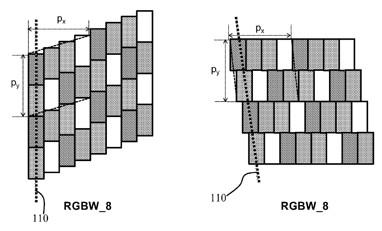
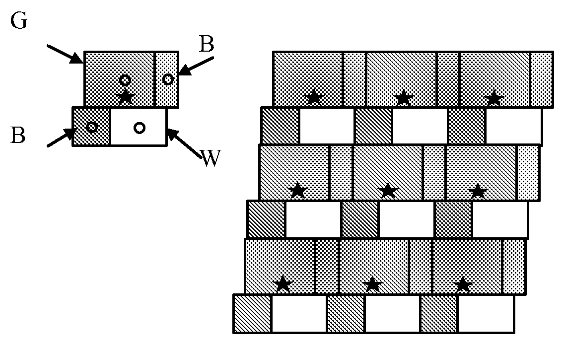
[0058] The present invention provides a lenticular autostereoscopic display device with a specific design (lens pitch and tilt angle) of the lenticular lens array to optimize the quality of the view presented to the user when using a pixel layout in which the color pixels have at least Four sub-pixels, these sub-pixels are at least three mutually different colors. The tilt angle and lens pitch are related to the pixel pitch (in row and column direction) and the number of sub-pixels of different colors.

[0059] Before describing the present invention in detail, reference will first be made to Figure 1 to Figure 3 Configurations of known autostereoscopic displays are described.

[0060] figure 1 , figure 2 and image 3 The known multi-view autostereoscopic display device in ® comprises a display panel 3, in this case an active matrix liquid crystal display (LCD) acting as image forming means.

[0061] The display panel 3 has an array of pixels arranged in orthogonal rows...


PUM


Abstract

The invention provides a autostereoscopic display device with a particular design of lenticular lens array (lens pitch and slant angle) to optimize the quality of the views provided to the user, when a multi-primary pixel layout is used, with at least four sub-pixels of at least three different colors. The slant angle and lens pitch is related to the pixel pitch (in the row and column directions) as well as the number of different color sub-pixels.

Description

technical field [0001] The present invention relates to an autostereoscopic display device having a display panel with an array of display pixels and a sensor for directing different views of an image displayed on the display panel into the field of view of the autostereoscopic display device Configurations for different physical locations. Background technique [0002] A known autostereoscopic display device is described in US patent 6064424. Without going into detail, the known device comprises a regular two-dimensional display panel having an array of rows and columns of display pixels, each display pixel having red, green and blue sub-pixels, the display panel serving as a image forming components. An array of elongated lenticular lenses overlies the display pixel array and serves as the view forming member, the elongated lenticular lenses extending parallel to one another with their elongated lenticular axes inclined relative to the pixel columns. The outputs from th...

Claims


Application Information

Patent Timeline
Patent Type & Authority Applications(China)
IPC IPC(8): H04N13/00H04N13/04G02B30/29
CPCH04N13/0422H04N13/0415H04N13/0404G02B27/2214H04N13/305H04N13/317H04N13/324G02B30/29H04N13/00G02B30/00G02B30/27
Inventor M.P.C.M.克里恩B.克鲁恩
Owner KONINKLJIJKE PHILIPS NV
Learn More