Positioning device between heat exchange tube and tube hole

A technology of positioning device and heat exchange tube, which is applied in auxiliary devices, auxiliary welding equipment, welding/cutting auxiliary equipment, etc. Problems such as low welding quality of tube sheet, to achieve the effect of improving welding quality and welding efficiency, and convenient operation and use

Active Publication Date: 2013-10-16
ZHANGHUAJI SUZHOU HEAVY EQUIP CO LTD
7 Cites 4 Cited by

AI-Extracted Technical Summary

Problems solved by technology

When welding, it is necessary to ensure that the heat exchange tube is concentric with the tube hole, and when the diameter of the heat exchange tube is smaller than the diameter of the tube hole on the tube plate, and the difference betwee...

Abstract

The invention discloses a positioning device between a heat exchange tube and a tube hole. The positioning device comprises a first positioning tube and a second positioning tube. The outer diameter of the first positioning tube is matched with the diameter of the tube hole in a tube sheet, and the first positioning tube can be sleeved inside the tube hole of the tube sheet in a close fit mode. The outer diameter of the second positioning tube is matched with the inner diameter of the heat exchange tube, and the second positioning tube can be sleeved outside the heat exchange tube in a close fit mode. The axis of the first positioning tube and the axis of the second positioning tube are the same. The first positioning tube and the second positioning tube are fixedly connected through a reduction nipple. The reduction nipple is flush with the outer wall of the first positioning tube and the outer wall of the second positioning tube respectively. The reduction nipple is provided with two welding holes which can conduct spot welding between the tube sheet and the heat exchange tube. The positioning device between the heat exchange tube and the tube hole has the advantages that the structure is simple and practical, operation and use are also very convenient and fast, and the welding quality and the welding efficiency for deep hole welding between the heat exchange tube and the tube sheet are greatly improved.

Application Domain

Technology Topic

EngineeringDeep hole +1

Image

  • Positioning device between heat exchange tube and tube hole
  • Positioning device between heat exchange tube and tube hole
  • Positioning device between heat exchange tube and tube hole

Examples

  • Experimental program(1)

Example Embodiment

[0010] The present invention will be further described in detail below with reference to the accompanying drawings and preferred embodiments.
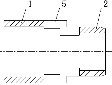
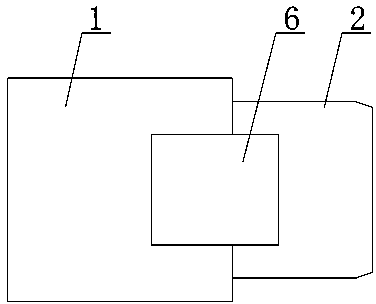
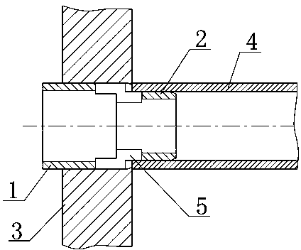
[0011] like figure 1 , figure 2 , image 3 As shown, the positioning device between the heat exchange tube and the tube hole includes a first positioning tube 1 and a second positioning tube 2. The outer diameter of the first positioning tube 1 is matched with the diameter of the tube hole on the tube sheet 3, and the first positioning tube 1 is matched with the diameter of the tube hole on the tube sheet 3. A positioning tube 1 can be tightly fitted in the tube hole of the tube sheet 3, the outer diameter of the second positioning tube 2 is matched with the inner diameter of the heat exchange tube 4, and the second positioning tube 2 can be tightly fitted in the heat exchange tube In the pipe 4, the axis lines of the first positioning pipe 1 and the second positioning pipe 2 are the same, and the first positioning pipe 1 and the second positioning pipe 2 are fixedly connected by the reducing pipe 5, and the reducing pipe 5 is connected with the first positioning pipe 5. The outer wall of the tube 1 and the reducing nozzle 5 is flush with the outer wall of the second positioning pipe 2 respectively. In this embodiment, the two sides of the reducing nozzle 5 are symmetrically opened with two spaces between the tube sheet 3 and the heat exchange tube 4 respectively. Weld holes 6 for spot welding.
[0012] The working principle is as follows: when the heat exchange tube 4 and the tube sheet 3 are deep-hole welded, if the outer diameter of the heat exchange tube 4 is smaller than the diameter of the tube hole of the tube sheet 3, and the difference between the two diameters is large, the No. The second positioning tube 2 is sheathed in the heat exchange tube 4, and then the first positioning tube 1 is sheathed into the tube hole of the tube plate 3, so that the axis line of the heat exchange tube 4 is the same as the axis line of the tube hole on the tube plate 3 , that is, the heat exchange tubes 4 are concentric with the tube holes on the tube sheet 3 . Extend the welding torch into the two welding holes 6 to spot-weld and fix the heat exchange tube 4 and the tube sheet 3 at the two welding holes 6 respectively, so as to fix the position of the heat exchange tube 4 and the tube hole, and then the heat exchange tube 4 and the tube hole can be fixed. The positioning device is pulled out and removed, and then the welding operation of deep hole welding can be performed on the heat exchange tube 4 and the tube sheet 3 .

PUM

no PUM

Description & Claims & Application Information

We can also present the details of the Description, Claims and Application information to help users get a comprehensive understanding of the technical details of the patent, such as background art, summary of invention, brief description of drawings, description of embodiments, and other original content. On the other hand, users can also determine the specific scope of protection of the technology through the list of claims; as well as understand the changes in the life cycle of the technology with the presentation of the patent timeline. Login to view more.

Similar technology patents

Classification and recommendation of technical efficacy words

  • Improve welding quality and welding efficiency
  • Easy to operate

Method for establishing large floating type wind power station tower drum

ActiveCN104526282AIncrease the substitutabilityImprove welding quality and welding efficiencyEngineeringWind power
Owner:JIANGSU MODERN SHIPBUILDING TECH

Welding robot for lidless box

ActiveCN107877060AImprove welding quality and welding efficiencyWelding/cutting auxillary devicesAuxillary welding devicesSeam weldingMotor shaft
Owner:华粹智能装备有限公司

Butt welding method for stainless steel clad steel plates

InactiveCN106270969AImprove corrosion resistance of weldsImprove welding quality and welding efficiencyArc welding apparatusSteel platesSubmerged arc welding
Owner:上海月月潮管道科技有限公司

Submerged-arc welding system for inner circle and outer circle of large cylinder

PendingCN111558766ARealize remote monitoring operationsImprove welding quality and welding efficiencyWelding/cutting auxillary devicesAuxillary welding devicesElectric machinerySubmerged arc welding
Owner:CHANGZHI QINGHUA MACHINERY FACTORY
Why Eureka
Try Eureka