
Punching and binding integrative machine

An all-in-one machine and punching device technology, applied in binding and other directions, can solve the problems of messing up the order of paper, taking a lot of time, and low binding efficiency, and achieve the effects of ensuring binding quality, convenient operation, and high work efficiency

Active Publication Date: 2013-10-16
ZHEJIANG ZHIYUAN OFFICE EQUIP MFG
View PDF10 Cites 7 Cited by
  • Summary
  • Abstract
  • Description
  • Claims
  • Application Information

AI Technical Summary

Problems solved by technology

This patent can only be used for punching holes. After the paper is punched, put the binding ring into the binding hole in a special binding machine to complete the binding. This method takes a lot of time, troublesome operation, and low efficiency. Especially when there are many papers to be bound, not only the binding efficiency is low, but also it is easy to mess up the order of the papers

Method used


Image

  • Punching and binding integrative machine
  • Punching and binding integrative machine
  • Punching and binding integrative machine

Examples


Embodiment 1

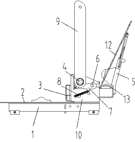
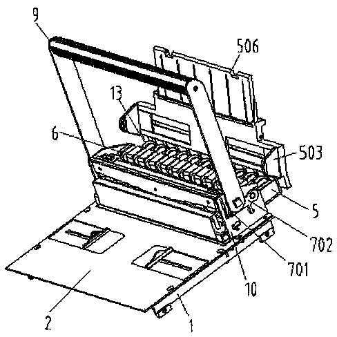
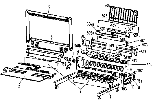
[0042] Embodiment 1, see attached figure 1 , 2, 3, 4, punching and binding all-in-one machine, including a base 1, a punching table 2 arranged on the base 1, a punching device 3 arranged on the base 1, and a rotatable mounting on the base 1 The rotating shaft 4 is fixed with a moving handle 9 on the rotating shaft 4, and the rotating shaft 4 is rotated by moving the handle 9 so that the punching device 3 completes the punching of the binding hole. The rotating shaft 4 is hinged on two brackets 10 Above, the rotating shaft 4 can be a polygonal prism shaft body or a cylinder. In this embodiment, it is a regular quadrangular prism with bushings 11 at both ends. The base 1 rotates to complete the punching of the paper, and the punched binding hole is mushroom-shaped, which is used to match the binding ring. In addition, it also includes the paper for placing the binding hole that has been punched and the binding hole that matches the binding hole. The placement device 5 of the r...

Embodiment 2

[0047] Embodiment 2, see attached Figure 5 , in this embodiment, the rotating part 701 includes a driving gear, the transition connecting part 702 includes a driven rack meshed with the driving gear, the driven rack is fixedly connected to the press-fit device 6, Drive the press-in device 6 to move linearly away from the rotation direction of the carrying handle 9 in the horizontal direction; the elastic return device can be a compression spring or a tension spring.

Embodiment 3

[0048] Embodiment 3, see attached Image 6 , the rotating part 701 includes a cam fixedly connected with the rotating shaft 4, the transition connecting part 702 includes a driven plate connected with the press-in device 6 for cooperating with the cam, and the guide The device 703 is a guide sleeve set on the driven plate, which acts as a guide for the driven plate, and the elastic return device can be a compression spring for pressing the driven plate or a tension spring for pulling the driven plate.


PUM


Abstract

The invention discloses a punching and binding integrative machine, which comprises a base, a punching table on the base, a punching device arranged on the base and a rotating shaft, and further comprises a placing device used for placing papers with binding holes, and binding rings matched with the binding holes, a pressing in device used for pressing the binding holes into the binding rings through exerting pressure on the papers, and a linkage device connected with the rotating shaft and used for converting the rotation of the rotating shaft into the movement that allows the pressing in device to press the binding holes into the binding ring so as to complete the paper binding, wherein the rotating shaft rotates around the base so as to finish the punching on the papers. The integrative machine is simple in structure, low in construction cost, and convenient to operate, is high in working efficiency and fast in speed as punching and binding are completed on one set of bookbinding machine, and realizes punching and binding at the same time. Moreover, the papers can be bound in batches, without messing the sequence.

Description

technical field [0001] The invention relates to the technical field of binding machines, in particular to a binding machine capable of both punching and binding. Background technique [0002] In existing binding machines, punching and binding are performed separately. For example, the Chinese utility model patent with the authorized announcement number CN 201026631Y and the authorized announcement date of 2008.02. It has a base, on which a knife rest fixing plate is installed, and a left frame and a right frame are respectively installed at both ends of the knife rest fixing plate, and a baffle plate is fixed between the left and right racks to form a channel-shaped bracket, and a channel-shaped bracket is formed between the bracket and the base. A paper insertion slot, a group of knife rests are fixed on the knife rest fixing plate, and each knife rest has a through hole whose shape is the same as that of the knife body. One end of the spring supports the bottom of the knif...

Claims


Application Information

Patent Timeline
Patent Type & Authority Applications(China)
IPC IPC(8): B42B5/08
Inventor 阮永华谭显斌蒋恩德
Owner ZHEJIANG ZHIYUAN OFFICE EQUIP MFG
Learn More