
Engine cooling circulation system with bypass cooling function and corresponding vehicle

A technology of engine cooling and circulation system, which is applied in the direction of engine cooling, engine components, machines/engines, etc. It can solve problems such as inability to adjust temperature, low integration, poor engine fuel consumption and emission performance, and reduce engine warm-up start time, cooling cycle system is compact, the effect of reducing fuel consumption and emissions

Active Publication Date: 2013-10-16
GREAT WALL MOTOR CO LTD
View PDF5 Cites 16 Cited by
  • Summary
  • Abstract
  • Description
  • Claims
  • Application Information

AI Technical Summary

Problems solved by technology

[0005] (1) The temperature of the cylinder block and the cylinder head water jacket cannot be adjusted independently, and it is difficult to realize the rapid warm-up of the engine during cold start, resulting in too long warm-up process of the engine cold start, and poor fuel consumption and emission performance of the engine running;
[0006] (2) The temperature of the turbocharger cannot be adjusted in a timely manner, which reduces the service life of the turbocharger;
[0007] (3) The thermostat seat in the prior art is cast on the cylinder head, resulting in many peripheral pipelines of the engine, the overall structure of the cooling system is complicated, the integration is low, and the assembly and maintenance performance of the thermostat seat is poor

Method used


Image

  • Engine cooling circulation system with bypass cooling function and corresponding vehicle
  • Engine cooling circulation system with bypass cooling function and corresponding vehicle
  • Engine cooling circulation system with bypass cooling function and corresponding vehicle

Examples


Embodiment 1

[0029] Embodiment 1 An engine cooling cycle system with split cooling function

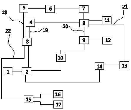
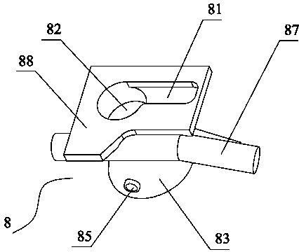
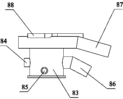
[0030] This embodiment provides an engine cooling cycle system with split cooling function, refer to figure 1 ,it includes:

[0031] The coolant tank 1, the coolant tank 1 is used to accommodate the coolant for cooling the engine system, and the coolant tank 1 provides the coolant for the water pump 2, specifically the water pump 2 pumps the coolant from the coolant tank 1 After taking it out, it flows into different parts through pipelines to cool down, including the cylinder block 3, that is, the coolant pumped by the water pump 2 enters the passage of the cylinder block 3.

[0032] The coolant flows out of the cylinder block 3 (after the coolant enters the channel of the cylinder block), and then flows into the water jacket 4 on the exhaust side of the cylinder head through the second diversion pipe 19, and at the same time flows in through the first diversion pipe 18 when the temperature o...

Embodiment 2

[0041] Embodiment 2 A vehicle

[0042] The present embodiment provides a vehicle including a cooling circulation system for cooling an engine.

[0043] The only difference between this vehicle and the prior art is that the cooling circulation system is the engine cooling circulation system provided by Embodiment 1 with a split function.

[0044] The structure of other parts of this vehicle is exactly the same as that of the vehicle in the prior art.


PUM


Abstract

The invention discloses an engine cooling circulation system with the bypass cooling function. The engine cooling circulation system comprises a cooling liquid box used for containing cooling liquid. The cooling liquid box is communicated with a water pump. A water outlet of the water pump is connected with a water inlet of an air cylinder body. A water outlet of the air cylinder body is connected with a water inlet of an air cylinder body water jacket through a first bypass pipeline. A first bypass switch controlled by cooling liquid temperature to open and close is arranged between the first bypass pipeline and the air cylinder body water jacket. The air cylinder body is further connected with a water inlet of an air cylinder cover exhaust side water jacket through a second bypass pipeline. A water outlet of the air cylinder body water jacket is converged with the water outlet of the air cylinder cover exhaust side water jacket and then enters an engine through the water pump. The invention further discloses a corresponding vehicle. The engine cooling circulation system is simple in structure, and capable of controlling the flow and the circulation path of cooling liquid according to the operation state of the engine, enables the engine to be heated quickly and start and reduces the oil consumption and emission of the engine at the same time, can cool a turbine booster and an intercooler, and prolongs the service life of the turbine booster and the service life of the intercooler. The engine cooling circulation system is applied to various vehicles.

Description

technical field [0001] The invention belongs to the field of automobiles, and in particular relates to the field of vehicle engine cooling, in particular to an engine cooling circulation system with split cooling function; the invention also provides a vehicle with the above-mentioned engine cooling circulation system. Background technique [0002] As vehicles increasingly enter people's daily lives, consumers are demanding more and more performance from them. As the heart component of the whole vehicle, the engine's performance directly reflects the performance of the vehicle itself, so ensuring the performance of the engine can guarantee the power performance of the vehicle. [0003] Since the engine will generate a lot of heat when it is running, if it is not treated in time, it will not only affect the running performance of the engine, but also affect the fuel performance of the engine, resulting in low fuel efficiency and more pollutants. Therefore, in order to ensure ...

Claims


Application Information

Patent Timeline
IPC IPC(8): F01P3/00F01P3/02F01P3/12F01P7/16
Inventor 李学超王文杰贾殿臣魏洪伟段景辉
Owner GREAT WALL MOTOR CO LTD
Learn More