Two-dimensional/three-dimensional switchable display

A display and three-dimensional technology, which is applied in the field of two-dimensional/three-dimensional switchable displays, can solve the problems that the curvature of the liquid crystal convex lens cannot reach the ordinary convex lens, cannot solve the crosstalk of the viewing area, and the accuracy is too high. The effect of strong sense and large focal length

Active Publication Date: 2015-07-01
HISENSE VISUAL TECH CO LTD
View PDF8 Cites 0 Cited by
  • Summary
  • Abstract
  • Description
  • Claims
  • Application Information

AI Technical Summary

Problems solved by technology

This solution requires too high accuracy in the moving distance, not only requires moving in the horizontal direction, but also moves outward for a certain distance in the vertical direction, and can only realize 2D / 3D display switching, and cannot solve the crosstalk problem of the visual zone
In addition, 2D / 3D display switching can also be achieved by adding a layer of liquid crystal layer to the original convex lens and controlling the liquid crystal layer to form convex lenses with different orientations. Limited by current technology, the curvature of the liquid crystal convex lens cannot reach the size of ordinary convex lenses, making 3D The three-dimensional effect is weakened, and only 2D / 3D display switching can be realized without solving the crosstalk problem of the viewing zone

Method used


Image

  • Two-dimensional/three-dimensional switchable display
  • Two-dimensional/three-dimensional switchable display
  • Two-dimensional/three-dimensional switchable display

Examples


Embodiment 1

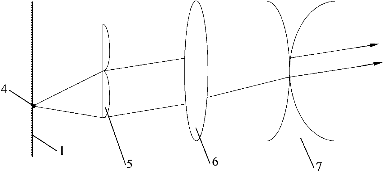
[0040] specifically, image 3 It shows the light transmission route diagram of the light emitted by a point light source on the display device after passing through the corresponding lenses when the 2D / 3D switchable display of this embodiment is in the 3D mode; Figure 4 for with image 3 When the corresponding two-dimensional / three-dimensional switchable display is in the two-dimensional mode, the light transmission route map of the light emitted by a point light source on the display device after passing through the corresponding lenses. refer to image 3 and Figure 4 As shown, in the present embodiment, the first lens grating layer is formed by a plano-convex lens, which is denoted as the first lens 5, the second lens grating layer is formed by a biconvex lens, and is denoted as the second lens 6, and the third lens grating layer is formed by a biconvex lens Formed, denoted as the third lens 7, the pitch of the second lens 6 and the third lens 7 are K (K is any integer)...

Embodiment 2

[0054] specifically, Figure 5 It shows the light transmission route diagram of the light emitted by a point light source on the display device after passing through the corresponding lenses when the 2D / 3D switchable display of this embodiment is in the 3D mode; Figure 6 for with Figure 5 When the corresponding two-dimensional / three-dimensional switchable display is in the two-dimensional mode, the light transmission route map of the light emitted by a point light source on the display device after passing through the corresponding lenses. refer to Figure 5 and Figure 6 As shown, in the present embodiment, the first lens grating layer is formed by plano-convex lenses, which is denoted as first lens 5, the second lens grating layer is formed by plano-convex lenses, and is denoted as second lens 6, and the third lens grating layer is formed by double-sided concave lenses. Form, record as the third lens 7, when using double-sided convex lens as the second lens 6, the radiu...

Embodiment 3

[0081] The structure of the 2D / 3D switchable display in this embodiment is similar to Embodiment 2, the difference is that in this embodiment, the lenses forming each lens grating layer are made of the same material, have the same refractive index, and have the same pitch.

[0082] specifically, Figure 7 It shows the light transmission route diagram of the light emitted by a point light source on the display device after passing through the corresponding lenses when the 2D / 3D switchable display of this embodiment is in the 3D mode; Figure 8 for with Figure 7 When the corresponding two-dimensional / three-dimensional switchable display is in the two-dimensional mode, the light transmission route map of the light emitted by a point light source on the display device after passing through the corresponding lenses. refer to Figure 7 As shown, when the display is in the three-dimensional mode, the second lenticular layer is separated from the third lenticular layer and a certai...


PUM


Abstract

The invention discloses a two-dimensional / three-dimensional switchable display and a method of controlling thereof. The display comprises a display device, and a first lenticulation layer, a second lenticulation layer, and a third lenticulation layer disposed in front of the display device, and a control unit. Divergent light emitted by a same point light source of the display device forms parallel light, converging light, and parallel light in sequence. The control unit controls the third lenticulation layer to move in a straight line along an optical axis thereof. When a front-side focus of the third lenticulation layer is overlapped with a front-side focus of the second lenticulation layer, a three-dimensional image is formed. When the front-side focus of the third lenticulation layer is not overlapped with the front-side focus of the second lenticulation layer, a two-dimensional image is formed. The two-dimensional / three-dimensional display is convenient to switch. In two-dimensional display, no resolution loss exists, and in three-dimensional display, visual area width reduces obviously and crosstalk is reduced, so that three-dimensional sensor is better, and display quality of the display is effectively improved.

Description

technical field [0001] The invention relates to the technical field of liquid crystal display, in particular to a two-dimensional / three-dimensional switchable display. Background technique [0002] At present, autostereoscopic display technology is developing rapidly under the active promotion of major manufacturers and the stimulation of increasing customer demand. Autostereoscopic display equipment allows people to get rid of the shackles of glasses in traditional stereoscopic display, allowing people to easily display at any time and anywhere. Feel free to experience the stereoscopic display effect of images or videos. At present, the mainstream method of autostereoscopic display is lens raster autostereoscopic display, which uses the refraction effect of the lens on the outgoing light to separate the light from different viewpoints, and then enters the left and right eyes of the person respectively, thereby achieving the effect of stereoscopic display. For details, plea...

Claims


Application Information

Patent Timeline
Patent Type & Authority Patents(China)
IPC IPC(8): G02B27/22H04N13/04
Inventor 张钦泉骆俊谕赵龙
Owner HISENSE VISUAL TECH CO LTD
Why Eureka
Try Eureka