Transport device with identification function

A technology of conveying device and marking device, applied in the direction of conveyor control device, conveyor, conveyor objects, etc., can solve the problem of difficult rotor monitoring, and achieve the effects of low identification, simple cost, and no pollution.

Inactive Publication Date: 2013-10-16
SYNTEGON TECHNOLOGY GMBH
View PDF7 Cites 19 Cited by
  • Summary
  • Abstract
  • Description
  • Claims
  • Application Information

AI Technical Summary

Problems solved by technology

Monitoring of the rotors can be difficult when there is a relatively long conveying path in such conveyors on which several rotors move

Method used


Image

  • Transport device with identification function

Examples


Embodiment Construction

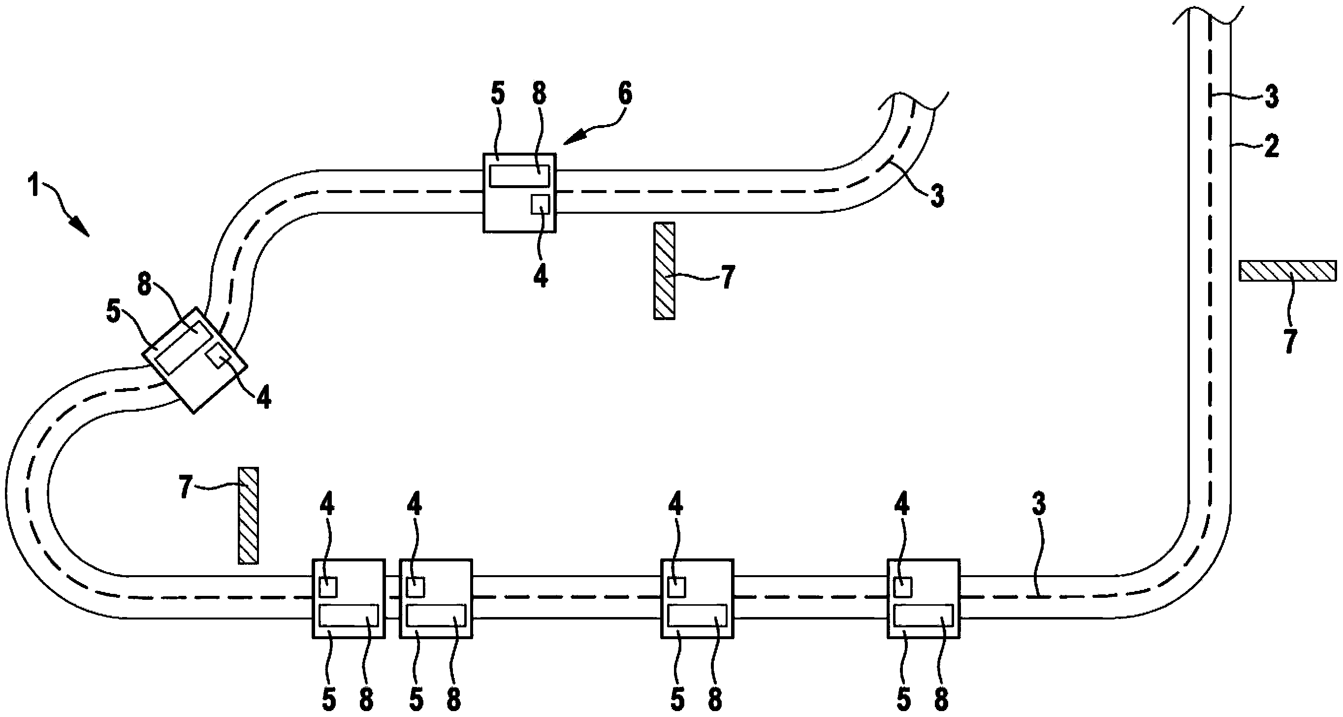
[0018] like figure 1 It can be seen that the conveying device 1 comprises a conveying section 2 and an electromagnetic drive. The electromagnetic drive comprises a plurality of coil elements 3 which are fixedly arranged on the conveying path 2 and a plurality of permanent magnets 4 , wherein each permanent magnet 4 is arranged on a rotor 5 . In this case, the individual coil elements 3 are controlled and energized independently of one another in order to move the rotor 5 along the conveying path 2 . The conveying path 2 can here be linear or closed all the way around.

[0019] The delivery device 1 also includes an individual identification device 6 , which includes a plurality of stationary sensors 7 and a plurality of individual marking devices 8 . The identification device 6 can include various sensors 7 and marking devices 8 , for example RFID sensors and RFID elements, Hall sensors and permanent magnets, incremental generator sensors and magnetic strips, or barcode sens...


PUM


Abstract

The present invention relates to a transport device for transporting products, in particular for feeding packaging machines, comprising a transfer section (2), an electromagnetic drive with a multiplicity of coil elements (3) and a multiplicity of permanent magnets (4), wherein the coil elements (3) are arranged in a stationary manner on the transfer section (2), a multiplicity of rotors (5) which are arranged movably on the transfer section (2), wherein at least in each case one permanent magnet (4) of the electromagnetic drive is arranged on a rotor (5), at least one sensor (7) which is arranged in a stationary manner on the transfer section (2), and individual marking devices (8) which can be detected by means of the sensor and which are in each case different from one another, wherein in each case at least one of the marking devices (8) is arranged on a rotor (5).

Description

technical field [0001] The invention relates to a conveying device for conveying products, in particular for filling packaging machines, in which rotors can be identified and tracked. Background technique [0002] A circular conveyor device is known from DE 10 2009 002 606 A1, which has an improved drive design. The known conveying device comprises a circumferential conveying path, at least one rotor and an electromagnetic drive having a plurality of stationary coil elements and a permanent magnet arranged on the rotor. Monitoring of the rotors can be difficult if a relatively long conveyor path is present in such a conveyor device over which several rotors move. However, it is necessary to know where the individual rotors are in order to control the electromagnetic drive. It is desirable to track the rotor and thus the products conveyed by the rotor over the entire conveying path. However such a system should be as simple and reliable as possible. Contents of the inven...

Claims


Application Information

Patent Timeline
Patent Type & Authority Applications(China)
IPC IPC(8): B65G54/02
CPCB65G54/02B65G2203/046B65G43/08
Inventor M·赖尼施H·范德勒西特
Owner SYNTEGON TECHNOLOGY GMBH
Why Eureka
Try Eureka