

Non-invasive blood glucose monitoring device and wearable noninvasive blood glucose meter
A technology for blood glucose monitoring and blood glucose meter, applied in the field of medical devices, can solve the problems of increasing patient pain, blood infection, inconvenience to carry, etc., to avoid the blood collection process, meet the monitoring requirements, and be easy to wear.
- Summary
- Abstract
- Description
- Claims
- Application Information
AI Technical Summary
Problems solved by technology
Method used
Image

Examples
Embodiment 1
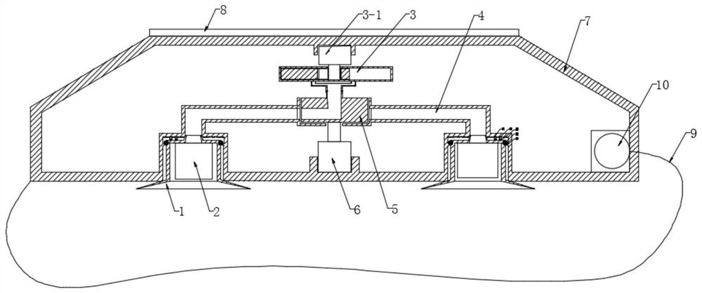
[0038] A non-invasive blood glucose monitoring device, such as figure 1 As shown, it includes a suction nozzle 1 that can be attached to the skin for collecting body fluids, an electronic detection module 2 installed inside the suction nozzle 1 for detecting the blood glucose level of the body fluid, and a negative pressure device that provides negative pressure for the suction nozzle 1. A pressure pump 3; the suction nozzle 1 communicates with the negative pressure pump 3 through an air guide tube 4.
[0039] After the negative pressure pump 3 is turned on, it provides negative pressure for the suction nozzle 1, and the suction nozzle 1 absorbs the body fluid on the skin surface under the negative pressure. The whole detection process is non-invasive detection.
[0040] Specifically, the suction nozzle 1 is as Figure 6 As shown, it includes a trumpet-shaped collection area 1-1 in contact with the skin, a detection area 1-2 for accommodating the electronic detection module ...
Embodiment 2
[0045] This embodiment introduces the detailed structure of its negative pressure pump on the basis of Embodiment 1.
[0046] The negative pressure pump 3 is as Figure 4 and Figure 5 As shown, it includes a negative pressure stepping motor 3-1, a triangular rotor 3-2 and a pump chamber 3-3; the triangular rotor 3-2 and the negative pressure stepping motor 3-1 pass through an eccentric shaft 3- 4 drive connection; the pump chamber 3-3 is composed of two symmetrical chambers; the triangular rotor 3-2 divides one of the chambers into a positive pressure area a and a negative pressure area b during rotation . For example, when the negative pressure stepper motor outputs torque, the eccentric shaft 3-4 drives the triangular rotor 3-2 to rotate clockwise, so that positive pressure is generated above the left chamber to form a positive pressure area a, and negative pressure is generated below the left chamber Become a negative pressure area b.
[0047] The positive pressure are...
Embodiment 3
[0050] A wearable non-invasive blood glucose meter, such as figure 1As shown, it includes a housing 7, an electronic screen 8, a strap 9 and the non-invasive blood sugar monitoring device as described in Embodiment 1 or 2; the non-invasive blood sugar monitoring device is installed inside the housing 7, wherein the collection area 1 of the suction nozzle 1- 1 is located outside the casing 7; the electronic screen 8 is installed on the outer surface of the casing 7.
[0051] The shell 7 is as Figure 7 As shown, its upper surface 7-1 is a plane for installing an electronic screen 8; its lower surface is provided with four grooves 7-2 for installing a suction nozzle 1;
[0052] Such as Figure 8 As shown, an annular protrusion 15 is provided on the inner wall of each said groove 7-2; a rubber ring 16 is installed on the outer wall of said suction nozzle 1; when installing, the suction nozzle 1 is inserted into the groove 7-2 , the rubber ring 16 is sealingly engaged with the ...
PUM
 Abstract
Description
Claims
Application Information