Vacuum cleaner

A vacuum cleaner and mop head technology, which is applied in the directions of suction nozzles, carpet cleaning, floor cleaning, etc., can solve the problems of aggravating the nozzle of the nozzle and the mop head to lift up, and achieve the effect of preventing lifting.

Inactive Publication Date: 2013-10-23
SUZHOU HAAN TECH +1
View PDF14 Cites 31 Cited by
  • Summary
  • Abstract
  • Description
  • Claims
  • Application Information

AI Technical Summary

Problems solved by technology

[0006]Due to the tilted center of gravity phenomenon described, when moving the vacuum cleaner back and forth to clean, especially when pulling the vacuum cleaner backwards, the front of the nozzle nozzle and the mop head lifts the upper part upwards, which eventually leads to the problem of reducing the vacuuming eff

Method used


Image

  • Vacuum cleaner
  • Vacuum cleaner
  • Vacuum cleaner

Examples


Example Embodiment

[0026] A preferred embodiment of the present invention will be described in detail below with reference to the accompanying drawings.

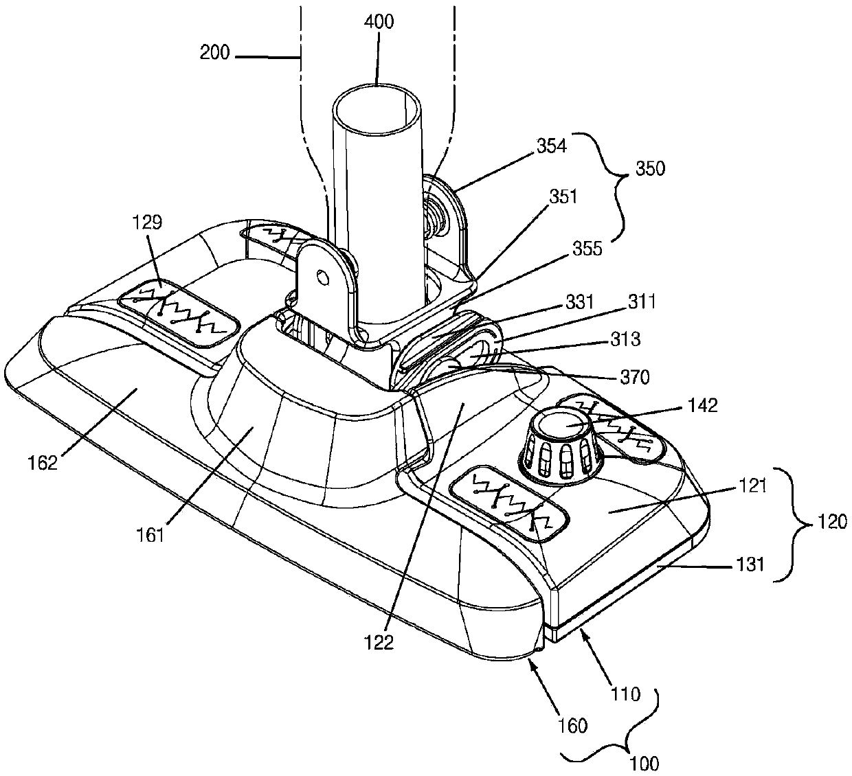
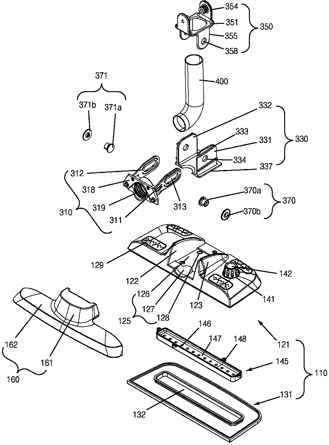
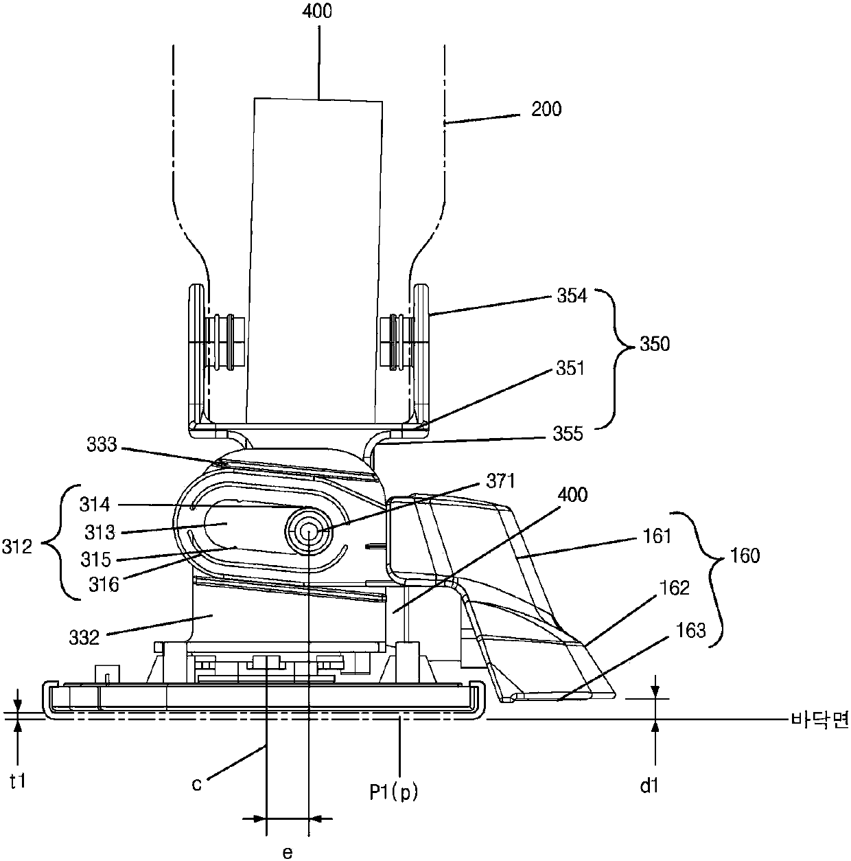
[0027] figure 1 In a preferred embodiment of the present invention, it is a schematic diagram of the connection between the mop head, the nozzle nozzle, the joint and the shell; figure 2 In a preferred embodiment of the present invention, it is an exploded schematic view of the mop head, the nozzle nozzle and the joint device; image 3 is in figure 1 , using a cleaning pad with a thickness of t1, and setting the side view of the nozzle nozzle at the rear position; Figure 4 is in figure 1 , using a cleaning pad with a thickness of t2 and setting the nozzle nozzle forward; Figure 5 It is a schematic cross-sectional view of the mop head in a preferred embodiment of the present invention.

[0028] like Figure 1 to Figure 5 As shown, the vacuum cleaner in a preferred embodiment of the present invention consists of the follo...


PUM


Abstract

The invention relates to a suction head assembly used for a vacuum cleaner in which a cleaning pad is disposed on a front end of a removable mophead and a sprayer-head nozzle can slide back and forth. The suction head assembly comprises a mophead, the sprayer-head nozzle which is slidably disposed on the front end of the mophead, and a front-and-back sliding component which makes the sprayer-head nozzle slide back and forth on the mophead. The sprayer-head nozzle of the suction head assembly can move back and forth on the mophead, so that the cleaning pad can be taken out or inserted simply.

Description

technical field [0001] The present invention relates to a vacuum cleaner. Background technique [0002] As Patent Document 1: U.S. Patent No. 7,137,169, Patent Document 2: U.S. Patent No. 7,293,322, the vacuum cleaner in the prior art consists of a mop head, a nozzle, a joint and a nozzle that can pass through the mop head. The hinge pin consists of a housing or push rod that rotates back and forth. [0003] The joint is located at the center (also in the left-right direction) between the front end and the rear end of the mop head. [0004] The joint is located at the upper center position of the mop head. [0005] Due to the central position of the adapter, the weight of the nozzle nozzle located in front of the mop head causes the center of weight to tilt forward. [0006] Due to the inclination of the center of gravity, when the vacuum cleaner is moved back and forth to clean, especially when the vacuum cleaner is pulled backwards, the nozzle and the front of the mop h...

Claims


Application Information

Patent Timeline
IPC IPC(8): A47L13/23A47L9/02
CPCA47L11/26A47L11/4044A47L11/408A47L11/4094
Inventor 韩京姬
Owner SUZHOU HAAN TECH
Why Eureka
Try Eureka