Mechanical and automatic wire inserting mechanism

An automatic and mechanical technology, applied in auxiliary devices, auxiliary welding equipment, welding/cutting auxiliary equipment, etc., can solve problems such as inability to meet the requirements of use, and achieve the effect of saving space, liberating productivity, and being easy to operate.

Active Publication Date: 2013-10-23
石家庄晶达建筑体系有限公司
View PDF10 Cites 4 Cited by
  • Summary
  • Abstract
  • Description
  • Claims
  • Application Information

AI Technical Summary

Problems solved by technology

In the process of welding the stressed steel bars of the shear wall with CL grid slabs, because the number of stressed steel bars (that is, abdominal bars) in the shear wall of CL grid slabs is very large, the inventor once disclosed a self-cutting steel wire Spot welding pliers (patent number 00225387.2), the basic design idea is to cut off the continuous steel wire during the welding process. For the construction site with a large amount of welding and a relatively large diameter of the steel wire, this kind of spot welding pliers still cannot meet the requirements for use.

Method used


Image

  • Mechanical and automatic wire inserting mechanism
  • Mechanical and automatic wire inserting mechanism
  • Mechanical and automatic wire inserting mechanism

Examples


Embodiment Construction

[0032] The present invention will be further described in detail below in conjunction with the accompanying drawings and specific embodiments.

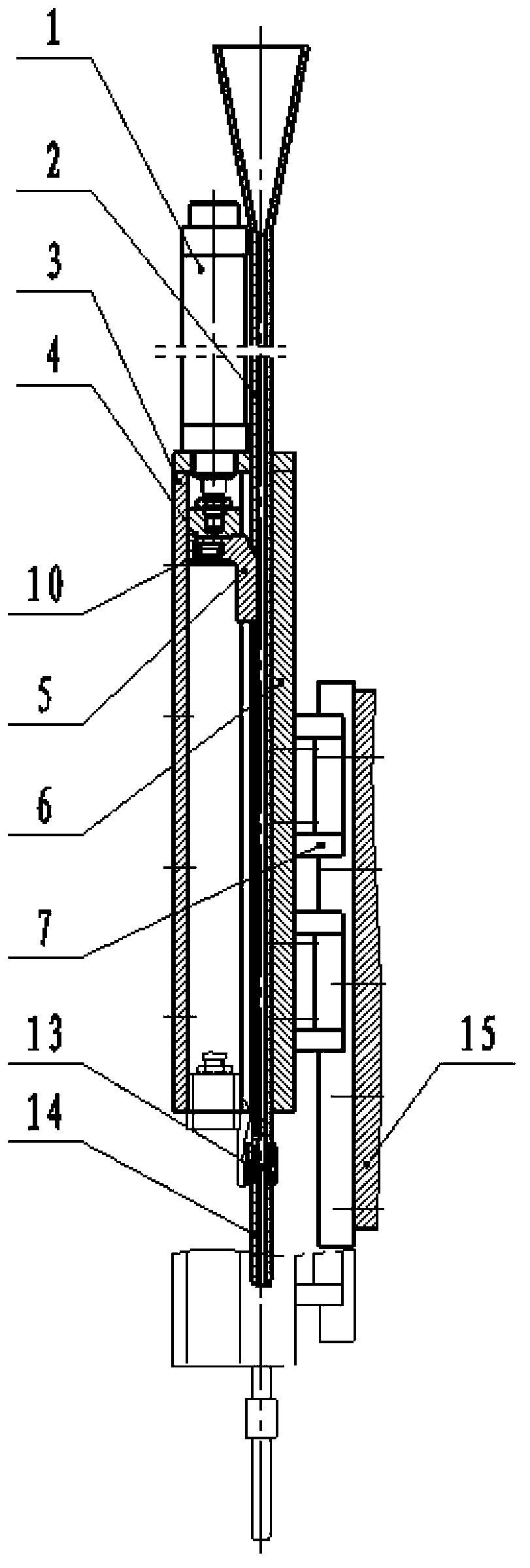
[0033] figure 1 , figure 2 , the structural features of the mechanical automatic wire insertion mechanism of the present invention shown, including: a wire insertion cylinder 1 and a guide tube 2 arranged in parallel, a guide seat 6 that fixes the wire insertion cylinder 1 and the guide tube 2, and a supporting structure thereof Guide plate 3, guide slider 4 is set on the wire insertion cylinder 1, and push rod 5 and push rod spring 10 are arranged on the guide slider 4, and guide slider 4 is driven along the guide seat 6 under the drive of wire insertion cylinder 1. The slider guide groove 17 performs reciprocating linear motion to form a wire insertion unit; the guide seat 6 is also provided with a displacement cylinder 9, and is connected to the fixed frame of the overall equipment through the linear guide rail pair 7;

[0034] ...


PUM


Abstract

The invention relates to a mechanical and automatic wire inserting mechanism, and belongs to the field of welding machinery or equipment. The mechanical and automatic wire inserting mechanism comprises a wire inserting air cylinder and a guide tube, parallelly arranged, a guide seat fixing the wire inserting air cylinder and the guide tube together and a guided plate playing a supporting role, wherein a guide sliding block is arranged on the inserting air cylinder; a push rod and a push rod spring are arranged on the guide sliding block; the guide sliding block carries out a reciprocating rectilinear motion along a sliding block guide groove in the guide seat under the drive of the wire inserting air cylinder to form a wire inserting unit; a displacement air cylinder is also arranged on the guide seat, and is connected with a fix frame of the whole equipment through a straight guide rail pair. The invention aims to the web bar wire inserting during the CL (composite light) net rack plate welding process, discloses a specially designed mechanical and automatic wire inserting mechanism and wire inserting method truncating the steel wire first then feeding wire one by one to weld, and can realize mechanized production operation of the CL net rack plate web bar wire inserting.

Description

technical field [0001] The invention relates to a mechanical automatic wire insertion mechanism, which belongs to the field of welding machinery or equipment, in particular to a mechanical automatic wire insertion mechanism and a wire insertion method used in continuous short steel wire welding operations, and is especially suitable for grids in CL building structure systems Automatic wire insertion of webs during frame plate welding. Background technique [0002] With the requirements of earthquake resistance, environmental protection and energy saving in modern houses, the CL building system is a CL grid plate formed by welding the insulation layer and the stressed steel bars of the shear wall in the factory, realizing the factory-like construction. In the process of welding the stressed steel bars of the shear wall with CL grid slabs, because the number of stressed steel bars (that is, abdominal bars) in the shear wall of CL grid slabs is very large, the inventor once dis...

Claims


Application Information

Patent Timeline
Patent Type & Authority Applications(China)
IPC IPC(8): B23K37/00
Inventor 张晶廷刘连升张海东刘立新张素辉刘会杰赵金池
Owner 石家庄晶达建筑体系有限公司
Why Eureka
Try Eureka