
Emergency escape device

An escape device and emergency technology, which is applied in the field of emergency escape devices, can solve the problems of not being able to pierce the glass, the sharp protrusions are not fully fixed, and the air is difficult to discharge, so as to avoid recoil obstruction and loss of impact force, and reduce visual recognition Time, the effect of increasing the chance of escape

Inactive Publication Date: 2013-10-23
石明
View PDF8 Cites 7 Cited by
  • Summary
  • Abstract
  • Description
  • Claims
  • Application Information

AI Technical Summary

Problems solved by technology

[0004] (1) It mainly uses compression software to support the hard floor, but the compression software is large and has a large contact area with the hard floor. When using hands or other tools to impact the hard floor, the compression software will instantly absorb a lot of impact The impact force is seriously lost and the glass cannot be punctured;
[0005] (2) Its hard bottom plate, compressed cushion and glass form a closed cavity. When hitting the hard bottom plate, the closed cavity is compressed, but the air inside is difficult to discharge, resulting in great recoil resistance and impact force. The loss is serious, and it is likely that the impact force of the impact glass cannot be achieved, resulting in failure to puncture the glass;
[0006] (3) The front end of the sharp protrusion used to pierce the glass is not sufficiently fixed, which may cause the sharp protrusion to slip, resulting in failure to pierce the glass

Method used


Image

  • Emergency escape device
  • Emergency escape device
  • Emergency escape device

Examples


Embodiment Construction

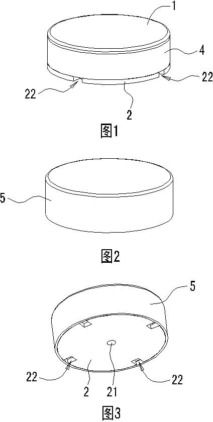
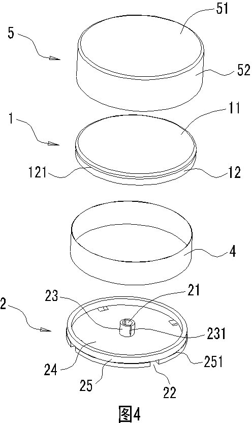
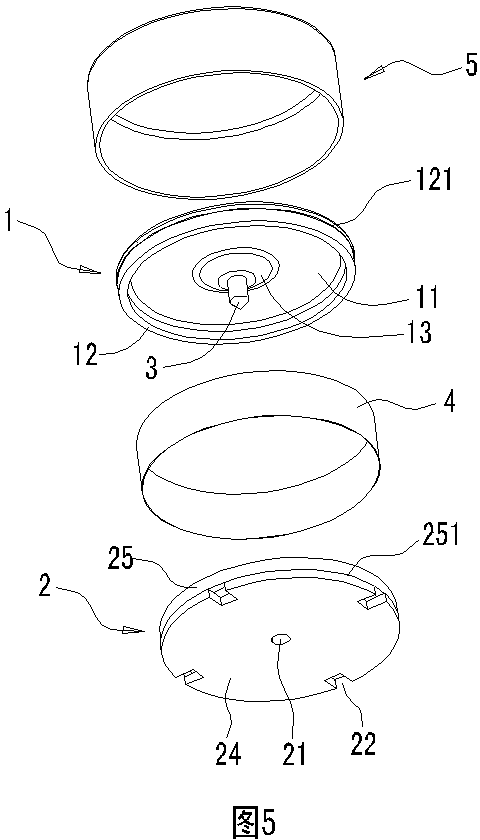
[0036] The present invention will be further described in detail below in conjunction with the accompanying drawings and specific embodiments.

[0037] Such as Figure 1 to Figure 13 As shown, an emergency escape device includes a gland 1, a bottom plate 2 that can be fixedly installed on the glass, and a crushing needle 3 fixedly installed on the gland 1, and an elastic soft body 4 is arranged between the gland 1 and the bottom plate 2, The gland 1 is supported on the base plate 2 by the elastic soft body 4, and the base plate 2 is provided with a through hole 21 for the crushing needle 3 to pass through to break the glass. The gland 1, the elastic soft body 4 and the base plate 2 together form a cavity A The crushing needle 3 is arranged in the cavity A and aligned with the through hole 21, and the gland 1 and / or the elastic soft body 4 and / or the bottom plate 2 are provided with a vent hole 22 for the air in the cavity A to discharge. In this embodiment, the ventilation ho...


PUM


Abstract

The invention relates to an emergency escape device, in particular to the emergency escape device, which is arranged on a glass window of various vehicles such as a bus, a coach, a school bus and a private car, or is arranged on other glass windows in emergency escape places and is used for fast breaking glass under the emergency condition. The emergency escape device comprises a press cover, a bottom plate and a breaking needle fixedly arranged on the press cover, wherein an elastic soft body is arranged between the press cover and the bottom plate, the press cover is born on the bottom plate through the elastic soft body, a through hole for the breaking needle to pass through for breaking the glass is formed in the bottom plate, the press cover, the elastic soft body and the bottom plate simultaneously surround a cavity, the breaking needle is arranged in the cavity and is aligned with the through hole, and ventilation holes for exhausting air in the cavity are formed in the press cover and / or the elastic soft body and / or the bottom plate. The emergency escape device has the advantages that when hands or other tools are used for beating the press cover, the cavity is pressed, the air in the cavity is exhausted from the ventilation holes, the backlash obstruction and the impact force loss are avoided, the glass can be fast punctured, and the fast escape under the emergency condition is realized.

Description

technical field [0001] The present invention relates to an emergency escape device, especially one that is installed on the glass windows of various vehicles such as buses, buses, school buses, private cars, etc., or installed on other glass windows in emergency escape places, used for Quickly smash the glass in an emergency to achieve a quick escape in an emergency. Background technique [0002] Few people would think of using the life-saving hammer used in emergency escape to break glass in the car on the market. Even when using it, because the head is not very sharp, it often takes many times to succeed. There is no way to smash the glass to escape. [0003] In view of the above problems, the Chinese invention patent No. ZL201320076630.8 discloses a "paste-type window breaker", which includes a hard base plate 1, sharp protrusions 2, a compressed soft pad 3 and a protective pad 4, the compressed The soft pad 3 is arranged on the outer ring of the hard base plate 1, and ...

Claims


Application Information

Patent Timeline
IPC IPC(8): B60R21/02
Inventor 石明
Owner 石明
Learn More