
Steel and concrete combined box girder concrete wing plate formwork and construction method

A technology of steel-concrete combination and construction method, applied in bridges, bridge construction, erection/assembly of bridges, etc., can solve the problems of difficult installation of wing plate formwork, difficult to ensure construction safety, and large impact on road traffic, so as to shorten the construction period and reduce processing time. The effect of low difficulty and low construction cost

Active Publication Date: 2013-10-23
CHINA RAILWAY SIXTH GROUP +1
View PDF3 Cites 9 Cited by
  • Summary
  • Abstract
  • Description
  • Claims
  • Application Information

AI Technical Summary

Problems solved by technology

However, this method requires the cooperation of the crane, and at the same time requires that there must be a site suitable for the hoisting operation under the bridge, and the hoisting operation has a great impact on the road traffic. In addition, the requirements for the crane driver are also high when occupying the road. When it is difficult to select the working site for the crane, the installation of the wing plate formwork will be extremely difficult
In addition, this construction method is not only difficult to guarantee the construction safety for the main road with a large traffic flow, but also increases the construction cost due to the long period of installation and removal of the support method.
In addition, this method has a greater safety risk in the construction of the wing plate

Method used


Image

  • Steel and concrete combined box girder concrete wing plate formwork and construction method
  • Steel and concrete combined box girder concrete wing plate formwork and construction method

Examples


Embodiment Construction

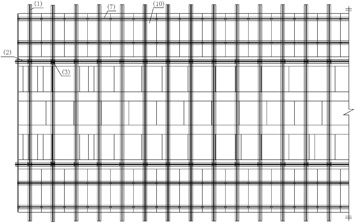
[0021] The steel-concrete combined box girder concrete wing plate template and construction method provided by the present invention will be described in detail below in conjunction with the accompanying drawings and specific embodiments.

[0022] Now take a certain project as an example: the project is located above the Fifth Ring Road in Beijing, in the middle of the Meishikou Highway Bridge, and uses a 36m steel-concrete combined box girder. Due to the construction of the box girder spanning the Fifth Ring Road, the construction process is affected by the traffic on the Fifth Ring Road, and the construction of the concrete wing plate is very difficult. During construction, it is considered that the bottom formwork of the wing plate should be in the form of non-demolition steel formwork, so as to reduce the span of five rings. Difficulty of ring road construction. The length of the flanges on both sides of the steel box girder is 2.358m, so the length of the concrete flange ...


PUM


Abstract

The invention discloses a steel and concrete combined box girder concrete wing plate formwork and a construction method. The formwork comprises a plurality of supporting cross beams, a plurality of supporting longitudinal beams, two supporting stand columns, a plurality of pull rods, a plurality of nuts, a plurality of gaskets, a plurality of longitudinal ridges, a plurality of steel cover plate brackets and a plurality of steel cover plates. The steel and concrete combined box girder concrete wing plate formwork and the construction method have the beneficial effects that the steel cover plates are arranged on top plates of erected steel box girders for forming a formwork system with the steel box girders, so that the problems of road crossing construction and non-bracket construction are solved, in the specific construction, the installation can be completed only by manual operation without the matching of large-scale hoisting equipment, and the elevation of a die block can be very conveniently and precisely adjusted, so that the precision is high; and in addition, for wing plates of different sizes, only formwork equipment with different specifications is needed to be manufactured, the used formwork equipment materials are fewer and are all common structural steel for engineering, the processing difficulty is small, the use is simple, and the site construction use is facilitated, so that the construction period is shortened, and the construction cost is low.

Description

technical field [0001] The invention belongs to the technical field of bridge construction auxiliary equipment, in particular to a steel-concrete combined box girder concrete wing plate template and a construction method. technical background [0002] With the rapid development of bridge construction, steel-concrete combined box girders are common. The wing plate is the main component of the steel-concrete box girder, and the wing plate formwork becomes an important component in the construction of the steel-concrete box girder. At present, the commonly used wing plate construction method is to use the bracket method to set up a door-shaped wing plate formwork system on the main road for construction work. However, this method requires the cooperation of the crane, and at the same time requires that there must be a site suitable for the hoisting operation under the bridge, and the hoisting operation has a great impact on the road traffic. When it is difficult to select the...

Claims


Application Information

Patent Timeline
IPC IPC(8): E01D21/00
Inventor 冯永起李玉川鹿红雷陈龙陈少武孙磊
Owner CHINA RAILWAY SIXTH GROUP
Learn More