Cam follower

A technology of cam follower and sliding cam, which is applied in the direction of engine components, transmissions, machines/engines, etc., can solve the problems of huge purchase and manufacturing costs, and achieve a good guiding effect

Inactive Publication Date: 2013-10-23
SCHAEFFLER TECH AG & CO KG
View PDF6 Cites 3 Cited by
  • Summary
  • Abstract
  • Description
  • Claims
  • Application Information

AI Technical Summary

Problems solved by technology

The new configuration of the cam follower with narrow rollers relative to the st

Method used


Image

  • Cam follower
  • Cam follower
  • Cam follower

Examples


Embodiment Construction

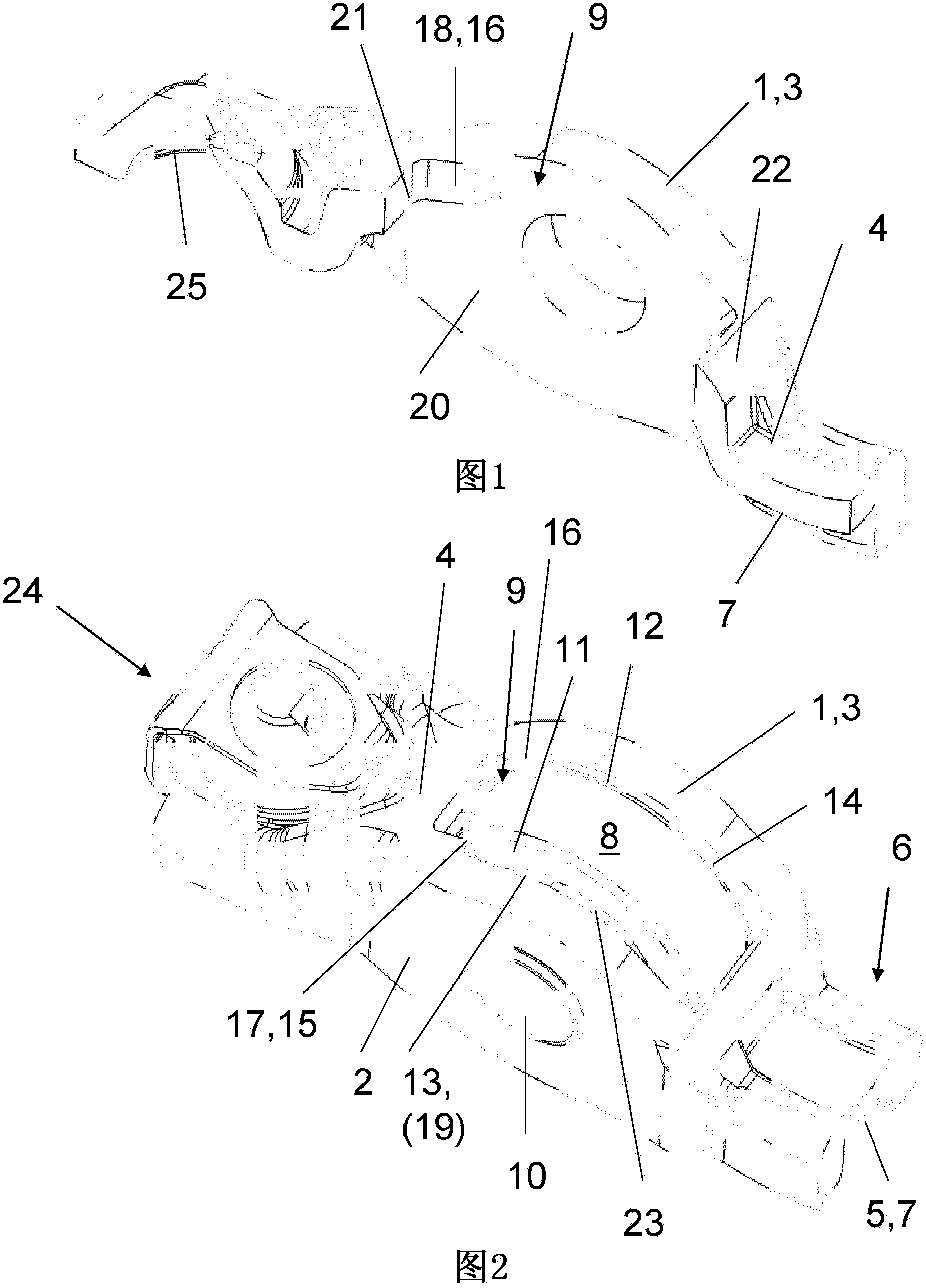
[0017] A cam follower 1 is shown as a sheet metal drawbar for a valve drive of an internal combustion engine. The cam follower has two substantially vertical side walls 2 , 3 which are connected by an upper crosspiece 4 such that an inverted U-shaped profile is formed in cross section.

[0018] On the underside 5 of the crosspiece 4 a device 7 for a ventilation valve is applied at one end 6 . On the other end 24 of the crosspiece 4 , on the underside 5 , a spherical segment-shaped contact surface 25 for the support element is shown.

[0019] The crosspiece 4 has a rectangular frame-like recess 9 penetrated by a roller 8 . The roller 8 is used for camming and in this case runs on a pin 10 placed in the side walls 2 , 3 via a bearing 23 . as by figure 2 As can be seen, a needle bearing arrangement is provided as bearing means 23 which extends with a slight axial play directly in front of the inner surfaces 19 , 20 of the side walls 2 , 3 . It can also be seen that the side ...


PUM


Abstract

The present invention relates to a cam follower. The cam follower has two side walls (2, 3) which are connected to each other through a crossbar (4) on whose underside (5), on one end (6), a support (7) for a gas exchange valve is disposed, wherein the crossbar (4) has a recess (9) through which a roller (8) extends, the roller (8) is supported via a bearing (23) on a pin (10) seated in the side walls (2, 3) and is at least used for indirect cam start. The cam follow is characterized in that the roller (8) is so narrow that outer front ends (11, 12) of the roller are clearly spaced from and out of contact with longitudinal surfaces (13, 14) of the recess (9), wherein at least one guide extension (15, 16) projects from each of the longitudinal surfaces (13, 14) towards a central longitudinal plane of the cam follower, and the roller (8) is guided on inner sides (17, 18) of the at least one guide extension.

Description

technical field [0001] The invention relates to a rod-shaped cam follower for a valve drive of an internal combustion engine, the cam follower having two side walls connected by a crosspiece, on the bottom side of the cam follower, applied at one end for Device for gas exchange valves in which the crosspiece has a recess penetrated by a roller running on a support mechanism on a pin placed in the side wall and used at least for indirect cam actuation. Background technique [0002] From document DE 10 2010 013 216 A1 figure 1 Such a cam follower is obtained from , here for a variable sliding cam valve drive of an internal combustion engine with an internal combustion system. [0003] For example, in today's cylinder head concepts of compact internal combustion engines with sliding cam valve control, only very little installation space is available for the necessary components. This means that, especially for camming, the rollers must be kept relatively narrow. Narrow rolle...

Claims


Application Information

Patent Timeline
IPC IPC(8): F01L1/047F01L13/00
CPCF16H25/14F01L1/181F01L1/185Y10T74/2107
Inventor 奥利弗·维特尔米夏埃尔·克雷斯
Owner SCHAEFFLER TECH AG & CO KG
Why Eureka
Try Eureka