
Control device of belt type continuously variable transmission

一种无级变速器、控制装置的技术,应用在传动装置、传动装置控制、带有齿的元件等方向,能够解决油压增加、油压降低、带夹持力降低等问题,达到防止滑动的效果

Active Publication Date: 2016-06-01
JATCO LTD
View PDF6 Cites 0 Cited by
  • Summary
  • Abstract
  • Description
  • Claims
  • Application Information

AI Technical Summary

Problems solved by technology

[0008] However, if the engine is stopped by coast stop control, the oil pump cannot operate, the oil pressure used for control decreases, and it is difficult to control the transmission ratio.
[0009] For example, when upshifting from a gear ratio in which the winding radius of the primary pulley is small, it is possible to upshift by increasing the primary pulley pressure, but it is difficult to increase the oil pressure when the engine is stopped, and the clamping force of the belt may reduce
In addition, when upshifting from a transmission ratio with a small winding radius of the primary pulley, although the upshift can be performed by discharging the secondary pulley pressure, if the hydraulic pressure is discharged too much, the hydraulic pressure will drop too much. , the clamping force of the belt may decrease
Therefore, even if the gear ratio is changed to a slip-suppressing gear ratio, the belt clamping force decreases during coast stop control, and belt slip may occur.

Method used


Image

  • Control device of belt type continuously variable transmission
  • Control device of belt type continuously variable transmission
  • Control device of belt type continuously variable transmission

Examples


Embodiment Construction

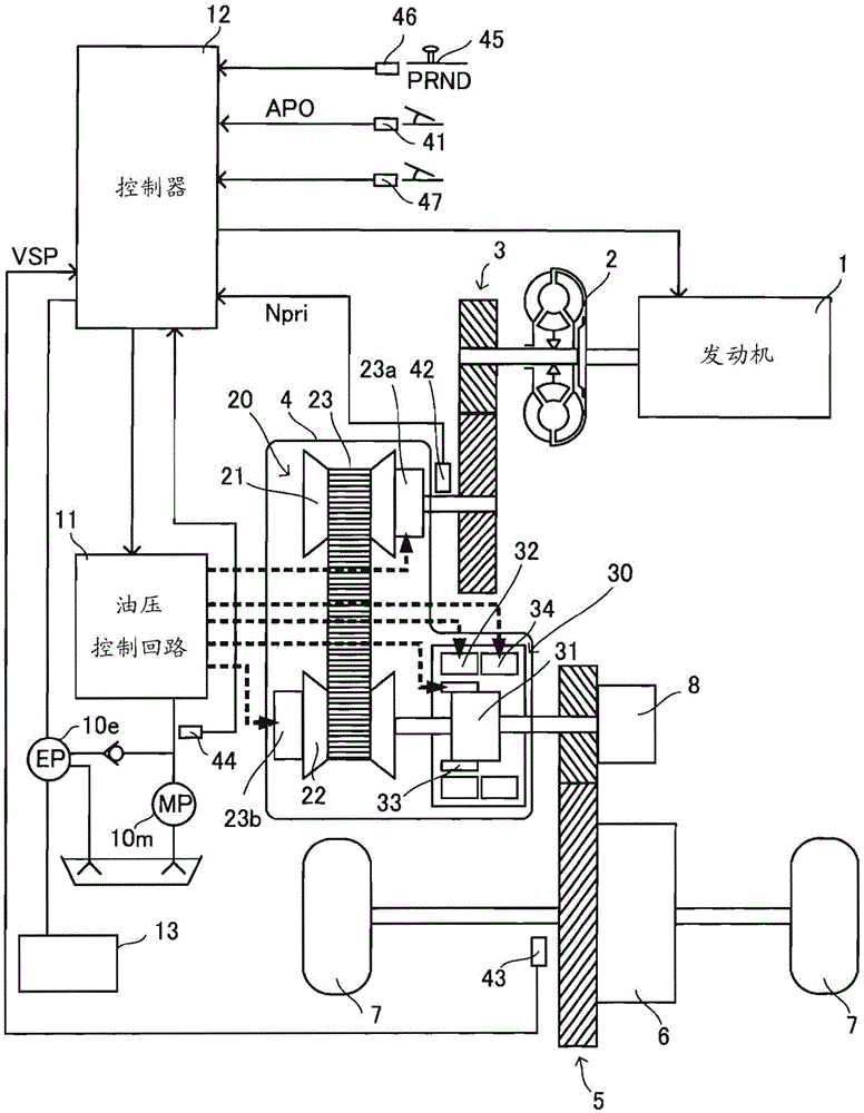
[0040] figure 1 It is a schematic configuration diagram of a vehicle on which the continuously variable transmission according to the first embodiment of the present invention is mounted. The vehicle includes an engine 1 as a power source. The output rotation of the engine 1 is transmitted to the drive wheels 7 via a torque converter 2 with a lock-up clutch, a first gear set 3 , a continuously variable transmission (hereinafter simply referred to as “transmission 4 ”), a second gear set 5 , and a final reduction device 6 . transfer. The second gear set 5 is provided with a parking mechanism 8 that mechanically locks the output shaft of the transmission 4 so that it cannot rotate when the vehicle is parked.

[0041] In addition, the vehicle is provided with a mechanical oil pump 10 m that inputs the rotation of the engine 1 and is driven by a part of the power of the engine 1 , and an electric oil pump 10 e that is driven by receiving electric power supply from the battery 13...


PUM


Abstract

The present invention provides a control device for a continuously variable transmission that prevents belt slip in an engine stop state. This continuously variable transmission is composed of a continuously variable transmission mechanism and a frictional engagement element, and the control device of the continuously variable transmission includes a control unit configured to enable the frictional engagement element to be activated during coast stop control for stopping a driving force source while the vehicle is running. The transmitted torque capacity is further lower than the belt capacity, which is the torque that can be transmitted by the belt using the clamping force of the pulleys.

Description

technical field [0001] The present invention relates to a speed change control device of a belt-type continuously variable transmission preventing belt slip. Background technique [0002] The oil pressure generated by the mechanical oil pump driven by the engine is supplied to the belt-type continuously variable transmission. The primary pulley and the secondary pulley are supplied with pulley pressure (primary pulley pressure and secondary pulley pressure) with this oil pressure as the primary pressure. The belt is clamped by these pulley pressures, and the groove width of each pulley is changed by controlling these pulley pressures to perform speed change. [0003] In a vehicle equipped with such a continuously variable transmission, for the purpose of improving fuel efficiency, so-called coast stop control in which the engine is stopped is performed not only when the vehicle is stopped but also before the vehicle is stopped. [0004] However, in the coast stop control, ...

Claims


Application Information

Patent Timeline
Patent Type & Authority Patents(China)
IPC IPC(8): F16H61/662
CPCB60W10/06B60W30/18072F16H61/66272B60Y2300/71B60W10/02B60W10/107B60W30/1846B60W2510/105B60W2710/027B60Y2300/46B60W2510/1075B60W2710/023Y02T10/60F16H59/14F16H61/04F16H61/06F16H61/12F16H61/66F16H9/16
Inventor 青山训卓若山英史山田直弘立胁敬一和久公佑
Owner JATCO LTD
Learn More