
Control apparatus for electrically driven vehicle

An electric vehicle and control device technology, which is applied in the control device, the safety device of the power device control mechanism, and the power-consuming device, etc., can solve the problem that the driving torque cannot be obtained, avoid or suppress the single-phase locked state, avoid or The effect of suppressing the loss of driving force and suppressing the decrease of the rotation speed

Inactive Publication Date: 2017-01-25
TOYOTA JIDOSHA KK
View PDF7 Cites 9 Cited by
  • Summary
  • Abstract
  • Description
  • Claims
  • Application Information

AI Technical Summary

Problems solved by technology

However, the engagement unit does not transmit torque because it is released, so the torque of the drive shaft becomes zero, and it may not be possible to obtain even the drive torque obtained in the case of single-phase locking.

Method used


Image

  • Control apparatus for electrically driven vehicle
  • Control apparatus for electrically driven vehicle
  • Control apparatus for electrically driven vehicle

Examples


Embodiment Construction

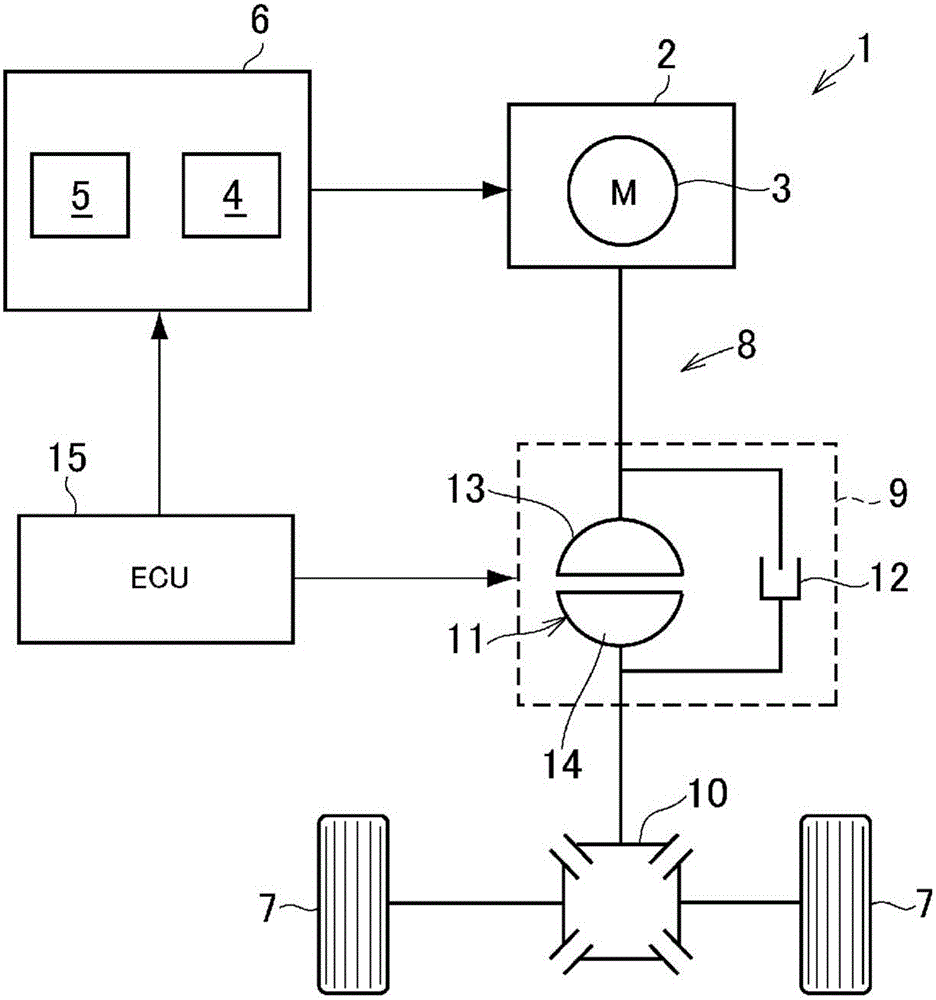
[0031] figure 1 An example of the electric vehicle 1 controlled by the control device of the present invention is schematically shown, and the driving force source 2 includes an electric motor (M) 3. The electric motor 3 is a three-phase synchronous electric motor as an example, and is configured to be supplied with power from a power supply unit 6 including a power storage device 4 and an inverter 5 to output power. It should be noted that, in addition to the electric motor 3, the driving force source may also include an internal combustion engine (not shown). Therefore, the electric vehicle 1 may be a so-called hybrid vehicle.

[0032] The transmission path 8 that transmits the power output from the electric motor 3 to the drive wheels 7 is provided with a differential gear 10 that allows differential rotation of the power transmission mechanism 9 and the left and right drive wheels 7 and transmits torque. The power transmission mechanism 9 includes a fluid coupling 11 and an e...


PUM


Abstract

The invention relates to a control apparatus for an electrically driven vehicle and an electrically driven vehicle. The single-phase locking state of the motor used for the driving power of the electrically driven vehicle is reliably prevented. The control apparatus for an electrically driven vehicle includes an electronic control unit and a dynamic power transmission mechanism. The electronic control unit is configured to control the dynamic power transmission mechanism to execute a slip control such that the speed of an electric motor is a higher speed than a speed of the electric motor at a predefined time point and speed of a relative rotation in the fluid coupling increases, in a case of determining that the operating state of the electric motor becomes the operating state in which the value of the heat load is the predetermined value or greater, the predefined time point being a time point when the operating state of the electric motor becomes the operating state in which the value of the heat load is the predetermined value or greater.

Description

Technical field [0001] The present invention relates to a control device for an electric vehicle that can run with an electric motor as a driving force source. Background technique [0002] In the case of using, for example, a three-phase synchronous motor as a motor, a state called single-phase lock may occur. Single-phase locking means that the thermal load generated by the motor within a predetermined period of time becomes a predetermined value or more, and the performance or performance of electric circuits or electronic circuits such as the motor or the inverter as its control device A state in which durability is reduced due to thermal load. Patent Document 1 describes a device configured to avoid or suppress such a state. The device described in Patent Document 1 is provided with an engagement unit between the rotating shaft and the drive shaft of a rotating machine such as a motor, and is configured to control the engagement unit to slide when it is determined that a s...

Claims


Application Information

Patent Timeline
Patent Type & Authority Applications(China)
IPC IPC(8): B60W10/08B60W10/02B60W20/00B60K6/36
CPCB60K6/36B60W10/02B60W10/08B60W20/00B60K17/02B60K28/165B60L3/0061B60L15/10B60L15/2054B60L2240/36B60L2240/421B60L2240/423B60L2240/429B60L2260/22B60L2260/50B60K6/445B60W30/1843B60Y2200/92Y10S903/902B60W2510/087Y02T10/72B60W10/023F16H61/38B60W2510/0275B60W2710/027F16D2500/70276B60W2556/00B60Y2300/42Y02T10/62Y02T10/64B60W10/10B60W10/026
Inventor 今村达也田端淳奥田弘一松原亨日浅康博今井惠太北畑刚
Owner TOYOTA JIDOSHA KK
Learn More