LED light source

A technology of LED light source and reflector, which is applied in the field of LED lighting, can solve problems such as light waste, insufficient lighting uniformity, and light dispersion obstruction, and achieve the effects of reducing light waste, improving luminous flux utilization rate, and improving road lighting uniformity

Inactive Publication Date: 2013-10-23
ADVANCED OPTRONIC DEVICES CHINA
View PDF13 Cites 2 Cited by
  • Summary
  • Abstract
  • Description
  • Claims
  • Application Information

AI Technical Summary

Problems solved by technology

The light distribution form obtained by the above two light distribution processes is a symmetrical batwing light distribution, that is: the C0-180 light distribution curve is a symmetrical batwing shape, and the C90-270 light distribution curve is a symmetrical approximately elliptical or approximately conical shape , but for street lighting applications, this form of light distribution is unreasonable, especially for motor vehicle lanes, this form of light distribution is lower than the utilization rate of lighting luminous flux of asymmetrical batwing light distribution
[0007] In the prior art, the process of realizing asymmetrical batwing light distribution through reflectors is: (1) An LED street lamp reflector module proposed by the Chinese patent application No. 201110414570.1. The light reflected by the polarized reflective surface is incident on the space area on the other side opposite to the polarized reflective surface, but there is no reflective structure on the opposite side of the polarized reflective surface of the reflector, causing the incident direction of some light to exceed the range of the lane, that is, it cannot be directly It irradiates the road surface of the road, causing a waste of light, which is reflected on the light distribution curve, that is, the beam angle of the curve on the C90-C270 plane is relatively large, especially the angle on the side of the positive angle is too large; (2) China with application number 201210584482.0 An LED light source module and its LED light source proposed in the patent application, and a LED light source proposed in the Chinese patent application with the application number 201310008008.8. The problem with these two technologies is the reflector with an asymmetric structure closed by the side wall , or a reflector with an asymmetric structure set around the LED single lamp on the side wall ring, so that the light is deflected to the side that is beneficial to street lighting, but the light is deflected to one side and the light is not evenly spread out according to the lighting range of the road surface , that is, the uniformity of illumination is not enough. The reason is that the reflector structures proposed by these two technologies are all closed side walls, or the side walls are ring-shaped and continuously surround the LED single lamp, which hinders the dispersion of light and reflects it to the distribution. On the light curve, that is, the maximum light intensity value of the curve on the C90-270 plane is obviously smaller than the maximum light intensity value of the curve on the C0-180 plane, and the maximum light intensity value of the curve on the C45-225 plane is obviously smaller than the maximum light intensity value of the curve on the C0-180 plane light intensity value

Method used


Image

  • LED light source
  • LED light source
  • LED light source

Examples


Embodiment 1

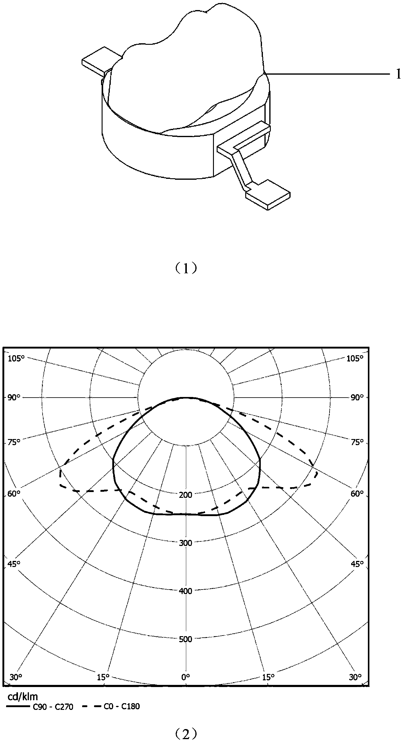
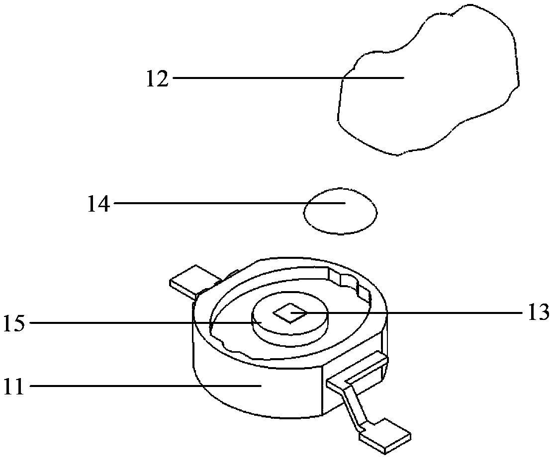
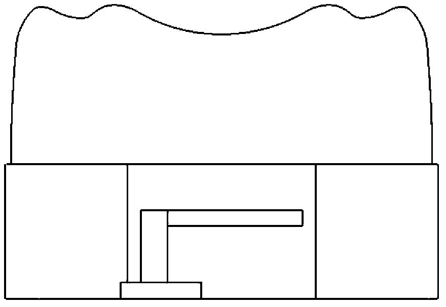
[0071] refer to figure 1 (1), figure 2 , image 3 , figure 1 (1) Structural schematic diagrams of the LED illuminants provided in Embodiments 1, 2, 3, and 4 of the present invention, figure 2 It is a schematic diagram of the structural decomposition of the LED illuminant provided in Embodiments 1, 2, 3, and 4 of the present invention, image 3 It is the front view of the LED illuminant provided by Embodiments 1, 2, 3 and 4 of the present invention. It can be seen from the figure that the LED illuminant 1 is an LED single lamp with a multi-peak lens 12 through a light distribution process, and is composed of a packaging bracket 11 , a multi-peak lens 12 , a light-emitting chip 13 and a fluorescent glue 14 . The center of the packaging bracket 11 is a cylindrical base 15, the light-emitting chip 13 is located at the center of the upper surface of the cylindrical base 15, and the fluorescent glue 14 is coated on the upper surface of the cylindrical base 15 and wraps the lig...

Embodiment 2

[0078] refer to Figure 12 , Figure 13 , Figure 14 , Figure 12 It is a schematic structural diagram of the reflector group provided in Embodiment 2 of the present invention, Figure 13 It is an exploded schematic diagram of the structure of the reflector group provided in Embodiment 2 of the present invention, Figure 14 It is a schematic structural diagram of the LED light source provided in Embodiment 2 of the present invention; it can be seen from the figure that the reflector group 2 is composed of two reflector units, which are reflector unit one 21, reflector unit two 22, and two reflector units respectively. The reflector units are not connected, and the first reflector unit 21 and the second reflector unit 22 have different structures and are respectively located on the front and rear sides of the LED illuminant 1 . The surface treatment of the reflector group 2 is a smooth surface such as vacuum aluminum plating, chrome plating, or silver plating, which is a sp...

Embodiment 3

[0083] refer to Figure 17 , Figure 18 , Figure 19 , Figure 17 It is a schematic structural diagram of the reflector group provided in Embodiment 3 of the present invention, Figure 18 It is an exploded schematic diagram of the structure of the reflector group provided by Embodiment 3 of the present invention, Figure 19 The structural representation of the provided LED light source for the present invention's implementation three; as can be seen from the figure, the reflector group 2 is made up of two reflector units, which are respectively reflector unit one 21, reflector unit two 22, two reflector units The reflector units are not connected, and reflector unit one 21 and reflector unit two 22 have different structural forms and are respectively located on the front and rear sides of the LED illuminant 1 . The surface treatment of the reflector group 2 is a smooth surface such as vacuum aluminum plating, chrome plating, or silver plating, which is a specular reflectio...


PUM


Abstract

The invention discloses an LED light source and an LED light source module formed by a plurality of the LED light sources. The LED light source comprises an LED luminous body and a reflector set, wherein the reflector set comprises two or more reflector units which are mutually independent; the horizontal cross section outline of the inner surface of each reflector unit is a straight line, or an inner arc-shaped curve, or an outer arc-shaped curve, or the combination of two line shapes; all reflector units are respectively arranged in different positions of the exterior of the LED luminous body, one reflector unit is respectively arranged before and after the front and rear sides of the LED luminous body, and the side wall of the reflector set is not closed, or discontinuous; one part of the ray sent out by the LED luminous body is reflected by the inner surface of the reflector set. The LED light source provided by the invention can achieve reasonable unsymmetric form batwing light distribution suitable for street lighting, so as to enable more rays to be guided to a direction having lighting utilization value, and unnecessary ray waste is reduced.

Description

technical field [0001] The invention relates to the technical field of LED lighting, in particular to an LED light source and an LED light source module composed of a plurality of such LED light sources. Background technique [0002] LED is easy to realize various forms of light distribution, and the corresponding LED light source can be formed through the primary light distribution process and the secondary light distribution process. The primary light distribution process is to package the lens on the packaging bracket in the process of making the LED package single lamp, so that it is integrated with the light-emitting chip, fluorescent glue and packaging bracket to form an LED single lamp. The common types of LED single lamps are: In-line type, SMD type, high-power package type, etc. Among them, the surface of the light-emitting chip is coated with fluorescent glue, and the lens is generally a silicone lens; this process is equivalent to a one-time realization in the pro...

Claims


Application Information

Patent Timeline
IPC IPC(8): F21S2/00F21V7/04F21V13/04F21Y101/02
CPCY02B20/72
Inventor 王慧东刘凯孙夕庆张彦伟孔瑞
Owner ADVANCED OPTRONIC DEVICES CHINA
Why Eureka
Try Eureka