Aircraft vertical stabilizer illumination light unit and method of operating an aircraft vertical stabilizer illumination light unit

a vertical stabilizer and illumination light technology, which is applied in the direction of aircraft lights, movable aircraft element position indicators, transportation and packaging, etc., can solve the problems of low maintenance requirements, large amount of wasted light from the light unit, and high reliability of the aircraft vertical stabilizer illumination light unit, so as to optimize the illumination of the vertical stabilizer and reduce the overall space requirements. , the effect of low overall space requirements

Active Publication Date: 2016-12-22
GOODRICH LIGHTING SYST GMBH
View PDF0 Cites 8 Cited by
  • Summary
  • Abstract
  • Description
  • Claims
  • Application Information

AI Technical Summary

Benefits of technology

[0019]According to a further embodiment, the aircraft vertical stabilizer illumination light unit has exactly one optical system, with all of the plurality of LEDs being associated with the exactly one optical system and with light output by the plurality of LEDs being affected differently by the exactly one optical system due to their different positioning with respect thereto. In this way, a high integration and low overall space requirements for the light unit can be achieved. The LEDs are all associated with the exactly one optical system, i.e. only one optical system is present that shapes the output light intensity distribution. Having different positions, each of the LEDs is affected differently by the optical system and, thus, contributes to the output light intensity in a different manner. By operating respective subsets of the LEDs, the different output light intensity distributions of the different operating modes can be achieved.
[0020]According to an alternative embodiment, the LED group comprises at least two LED sub-groups and the optical system comprises at least two optical sub-systems, with each LED sub-group forming an optical set with a respective optical sub-system and with each optical set being optically independent from the other optical sets. In this way, optical sets are provided that may be designed independently from each other. Each optical set may be optimized for a particular contribution to the output light intensity distribution. In this way, the output light intensity distributions may be the result of the combined operation of different optical sets, which may lead to a more optimized illumination of the vertical stabilizer across the different operating modes. This approach may lead to more degrees of freedom in the design of the light unit for a particular application. It is possible that the LED sub-groups consist of one LED. However, it is also possible that there are multiple optical sets, as described above, and that each or some of the multiple optical sets have several LEDs contained therein. In this way, an optimized compromise between highly accurate light output and low space requirements may be achieved.
[0021]According to a further embodiment, the aircraft vertical stabilizer illumination light unit comprises a rotation angle sensor configured to sense the rotation angle of the horizontal stabilizer. In this way, the aircraft vertical stabilizer illumination light unit is an independent system that can adjust the output light intensity distribution without requiring input data.

Problems solved by technology

In other words, such a prior art vertical stabilizer illumination light unit emits a large amount of “wasted” light.
This leads to a high reliability of the aircraft vertical stabilizer illumination light unit and, thus, to low maintenance requirements.
This may lead to low power consumption and / or a high lifetime of the light unit.

Method used


Image

  • Aircraft vertical stabilizer illumination light unit and method of operating an aircraft vertical stabilizer illumination light unit
  • Aircraft vertical stabilizer illumination light unit and method of operating an aircraft vertical stabilizer illumination light unit
  • Aircraft vertical stabilizer illumination light unit and method of operating an aircraft vertical stabilizer illumination light unit

Examples


Embodiment Construction

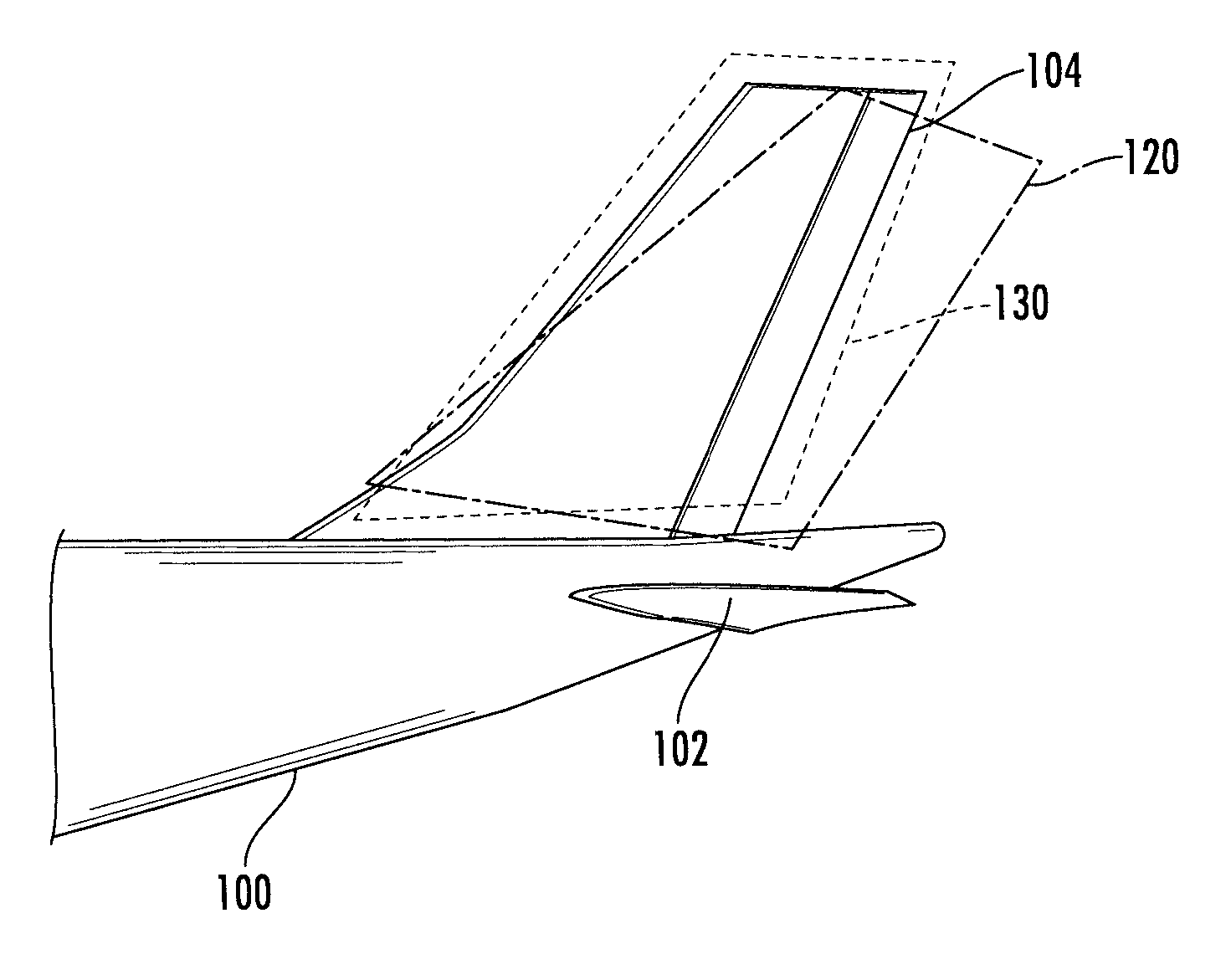
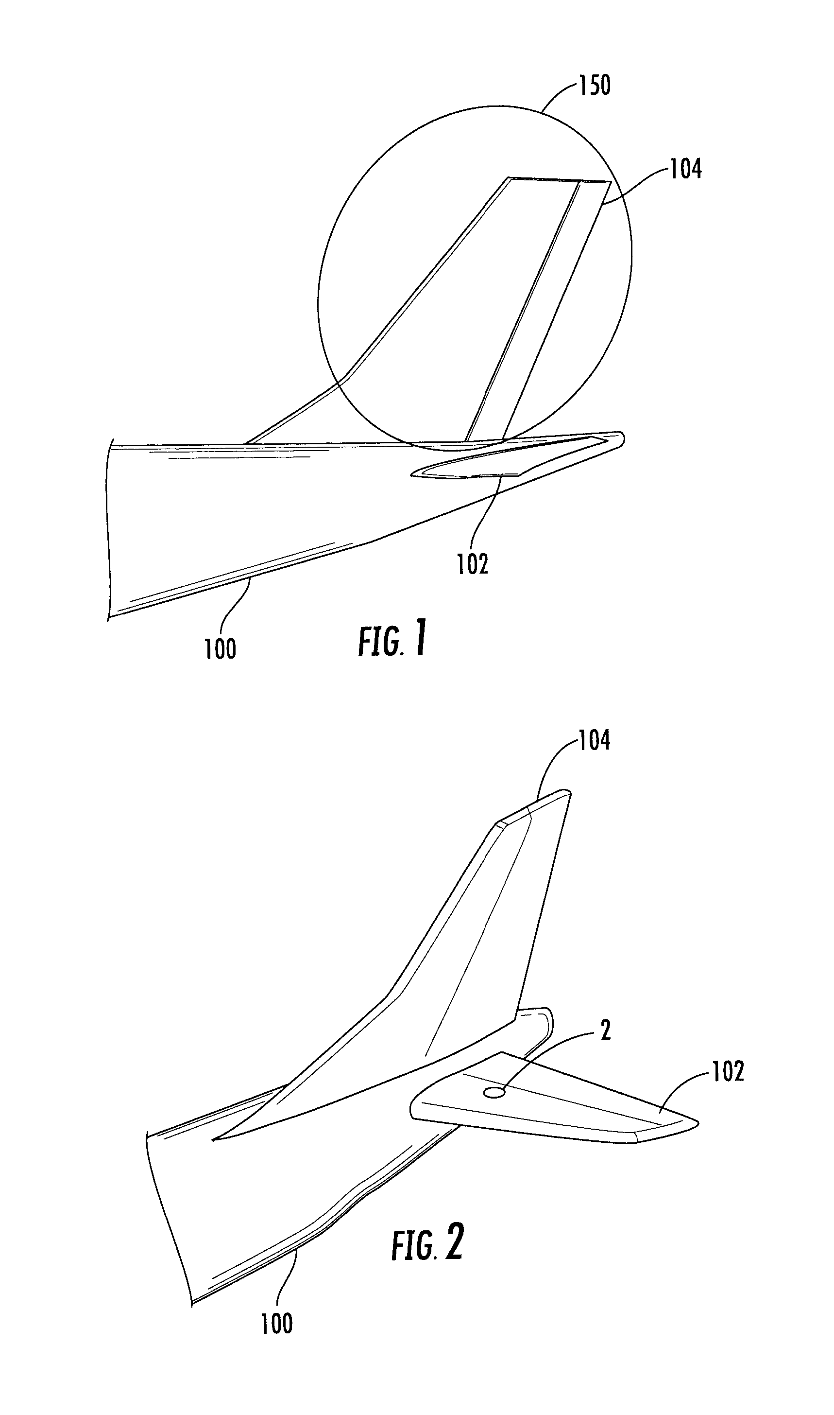
[0033]FIG. 2 shows a tail portion of an aircraft 100 in a perspective view. In the perspective view of FIG. 2, a left rotatable horizontal stabilizer 102 and a vertical stabilizer 104 are shown, which are mounted to the fuselage of the aircraft 100. The left rotatable horizontal stabilizer 102 comprises an aircraft vertical stabilizer illumination light unit 2 in accordance with exemplary embodiments of the invention. The aircraft vertical stabilizer illumination light unit 2 is disposed on the upper side of the left rotatable horizontal stabilizer 102. It is arranged within the body of the left rotatable horizontal stabilizer 102 and has a cover lens that is flush with the upper surface of the left rotatable horizontal stabilizer 102. The aircraft vertical stabilizer illumination light unit 2 in operation emits light through the cover lens towards the vertical stabilizer 104 and illuminates the same. As will be explained in detail below, the aircraft vertical stabilizer illuminatio...


PUM


Abstract

An aircraft vertical stabilizer illumination light unit, configured for being arranged in a rotatable horizontal stabilizer of an aircraft and for being oriented towards a vertical stabilizer of the aircraft for illuminating the vertical stabilizer, includes an LED group, having a plurality of LEDs, and an optical system, having at least one optical element, the optical system being associated with the LED group for shaping an output light intensity distribution from the light emitted by the LED group.

Description

FOREIGN PRIORITY[0001]This application claims priority to European Patent Application No. 15 172 851.6 filed Jun. 19, 2015, the entire contents of which is incorporated herein by reference.TECHNICAL FIELD[0002]The present invention is in the field of exterior aircraft lighting. In particular, the present invention relates to light units for the illumination of the vertical stabilizer at the tail of an aircraft. Such light units are sometimes also referred to as logo lights.BACKGROUND OF THE INVENTION[0003]Large commercial aircraft have many different exterior lights. An exemplary group of exterior aircraft lights are lights for passive visibility, such as navigation lights and anti-collision lights. Another exemplary group of exterior aircraft lights are headlights that allow the pilots to view the area in front of them, when they are seated in the cockpit, such as taxi lights, take-off lights, landing lights, and runway turn-off lights. Yet another example of exterior aircraft ligh...

Claims


Application Information

Patent Timeline
Patent Type & Authority Applications(United States)
IPC IPC(8): B64D47/06B64C5/02B64D45/00B64C5/16
CPCB64D47/06B64D45/0005B64C5/02B64C5/16B64D47/02B64D2203/00
Inventor LUEDER, SASCHA
Owner GOODRICH LIGHTING SYST GMBH
Why Eureka
Try Eureka