Optical lens linear motion zoom optical system

A technology of linear motion and optical lens, applied in the field of optical lens linear motion zoom optical system, optical lens zoom system, can solve the problems of large equipment volume, high manufacturing cost, low zoom precision, etc., to eliminate large backlash and improve precision and work efficiency, meeting the requirements of precision tracking and measurement

Inactive Publication Date: 2013-10-23
XI'AN INST OF OPTICS & FINE MECHANICS - CHINESE ACAD OF SCI
View PDF7 Cites 12 Cited by
  • Summary
  • Abstract
  • Description
  • Claims
  • Application Information

AI Technical Summary

Problems solved by technology

[0008] The invention provides a linear motion zoom optical system of an optical lens, which solves the problems of low zoom accuracy, high manufacturing cost, large equipment volume, and non-adjustable motion curves of existing mechanical compensation continuous zoom optical devices.

Method used


Image

  • Optical lens linear motion zoom optical system
  • Optical lens linear motion zoom optical system

Examples


Embodiment Construction

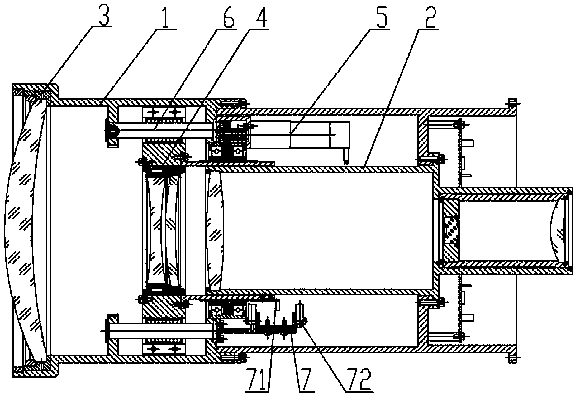
[0025] The present invention provides an optical lens linear motion zoom optical system, see attached figure 1 , a fixed frame 1 with a cavity inside, a first lens group 2 and a second lens group 3 respectively fixed at both ends of the fixed frame 1, and a zoom lens assembly 4 arranged between the first lens group 2 and the second lens group 3 , the driving device 5 for providing the zoom lens assembly 4 with reciprocating linear motion, and at least three sets of guide assemblies 6 fixedly arranged and evenly distributed on the inner surface of the fixed frame 1 for supporting and guiding the zoom lens assembly 4 .

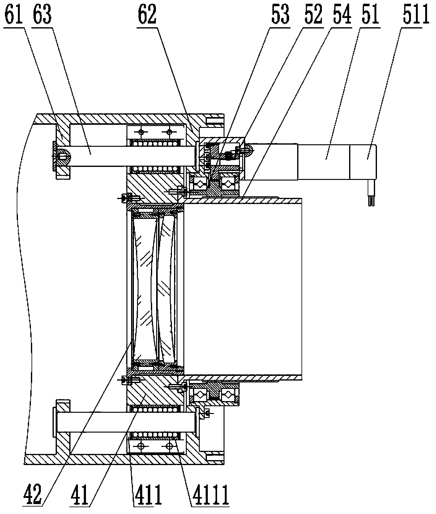
[0026] Such as figure 2 As shown, the zoom lens assembly 4 includes a moving mirror frame 41, a zoom lens group 42 installed in the inner hole of the moving mirror frame 41; the moving mirror frame 41 is provided with a through hole 411 corresponding to the position of the guide assembly 6; the guide assembly 6 passes through the moving The through hole 411 on...


PUM


Abstract

The invention belongs to the optical field, and particularly relates to an optical lens linear motion zoom optical system. The system comprises a fixing frame with the interior being a cavity, a first lens set, a second lens set, a zoom lens assembly, a driving device and at least three sets of guide assemblies, wherein the first lens set and the second lens set are fixed at the two ends of the fixing frame respectively, the zoom lens assembly is arranged between the first lens set and the second lens set, the driving device is used for enabling the zoom lens assembly to make reciprocating linear motion, the at least three sets of guide assemblies are fixedly arranged and evenly distributed on the inner surface of the fixing frame, and the at least three sets of guide assemblies are used for supporting and guiding the zoom lens assembly. According to the optical lens linear motion zoom optical system, the problems that an existing mechanical compensation continuous zoom optical device is low in zoom accuracy, high in manufacturing cost, large in equipment size and non-adjustable in motion curve are solved.

Description

technical field [0001] The invention belongs to the field of optics, and relates to an optical lens zoom system, in particular to an optical lens linear motion zoom optical system. Background technique [0002] Mechanically compensated continuous zoom optical system, the traditional method is mainly to use a mechanical cam mechanism to realize the continuous zoom of the zoom optical lens. There are various types of mechanical cams, which are divided into three types: disc cams, moving cams, and cylindrical cams according to the cam shape. In the lens movement mechanism, a cylindrical cam is mainly used. There are two groups of curved grooves on the circumference of the cam, and the two groups of grooves are processed according to the optical performance curve, so that when the zoom group moves, the compensation group moves accordingly for compensation. [0003] In the mechanical cam mechanism, there are mainly rotating motors, cams, guide pins, moving mirror groups, and ou...

Claims


Application Information

Patent Timeline
Patent Type & Authority Applications(China)
IPC IPC(8): G02B7/10G02B15/15
Inventor 王苗郝伟曹焱
Owner XI'AN INST OF OPTICS & FINE MECHANICS - CHINESE ACAD OF SCI
Why Eureka
Try Eureka