A lamp and a power switch control circuit

A technology for controlling circuits and power switches, applied to electronic switches, lamp circuit layout, electric light sources, etc., can solve problems such as easy failures

Active Publication Date: 2013-10-23
OCEANS KING LIGHTING SCI&TECH CO LTD +1
View PDF3 Cites 3 Cited by
  • Summary
  • Abstract
  • Description
  • Claims
  • Application Information

AI Technical Summary

Problems solved by technology

[0003] The technical problem to be solved by the present invention is to provide a power switch control circuit for the above-mentioned mechanical switch in the prior art, which is prone to malfunction due to a large current passing through when the switch is in operation. Small signal controls large current, less prone to failure

Method used


Image

  • A lamp and a power switch control circuit
  • A lamp and a power switch control circuit
  • A lamp and a power switch control circuit

Examples


Embodiment Construction

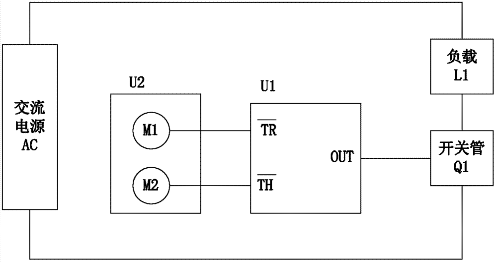
[0019] Such as figure 1 As shown, in the logic structure diagram of Embodiment 1 of the power switch control circuit of the present invention, the power switch control circuit is used to control the on-off of the load L1, and the power switch control circuit includes a 555 timer U1, a switch module U2, a switch Tube Q1 and AC power supply AC, wherein the switch module U2 includes an opening metal sheet M1 and an closing metal sheet M2 for the user to touch, and the setting terminal (TR) of the 555 timer U1 is connected to the opening metal sheet M1, and the 555 timer The reset terminal (TH) of U1 is connected to the shut-off metal sheet M2, the output terminal (OUT) of the 555 timer U1 is connected to the control terminal of the switch tube Q1, the first terminal of the switch tube Q1 is connected to the first terminal of the load L1, and the load L1 The second end and the second end of the switch tube Q1 are respectively connected to two ends of the alternating current power ...


PUM


Abstract

The invention discloses a lamp and a power switch control circuit. The power switch control circuit comprises a 555 timer, a switch module, a switching tube, and an AC power supply. The switch module comprises a turning-on metallic sheet and a turning-off metallic sheet which are used for being touched by a user. The setting end of the 555 timer is connected with the turning-on metallic sheet while the resetting end of the 555 timer is connected with the turning-off metallic sheet. The output end of the 555 timer is connected with the control end of the switching tube. The first end of the switching tube is connected with the first end of a load. The second end of the load and the second end of the switching tube are connected with the two ends of the AC power supply, respectively. When the technical scheme of the invention is executed, the power switch control circuit achieves large current control with a small signal because a conventional mechanical switch is replaced by a touch switch. Therefore, faults caused by a fact that large current passes through the mechanical switch when the mechanical switch performs switch operation can be prevented.

Description

technical field [0001] The invention relates to a power switch, in particular to a lamp and a power switch control circuit thereof. Background technique [0002] In recent years, with the diversification of the functions of household appliances, the number of switches used to control household appliances is also increasing, but these switches are mostly traditional mechanical switches. In the power switch control circuit, due to the mechanical switches There will be a large current passing through during the action, so it is easy to cause the switch to ignite, oxidize, etc., which will cause the mechanical switch to fail due to poor contact. Contents of the invention [0003] The technical problem to be solved by the present invention is to provide a power switch control circuit for the above-mentioned mechanical switch in the prior art, which is prone to failure due to a large current passing through when the switch is in operation. Small signal controls large current an...

Claims


Application Information

Patent Timeline
Patent Type & Authority Applications(China)
IPC IPC(8): H03K17/96H05B37/02
CPCY02B20/42Y02B20/40
Inventor 周明杰管伟芳
Owner OCEANS KING LIGHTING SCI&TECH CO LTD
Why Eureka
Try Eureka