Monitoring method and device

A control method and equipment technology, which is applied in the field of network communication, can solve the problems of increasing equipment power consumption and blindness in the monitoring process, and achieve the effect of reducing power consumption and meeting the requirements of data transmission

Inactive Publication Date: 2016-03-09
HUAWEI TECH CO LTD
View PDF4 Cites 0 Cited by
  • Summary
  • Abstract
  • Description
  • Claims
  • Application Information

AI Technical Summary

Problems solved by technology

[0004] The embodiment of the present invention provides a monitoring control method and equipment to solve the problem that the existing equipment monitors blindly in the monitoring process according to the DRX cycle and easily increases the power consumption of the equipment

Method used


Image

  • Monitoring method and device
  • Monitoring method and device
  • Monitoring method and device

Examples


no. 1 example

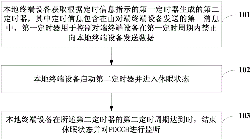
[0026] see figure 1 , which is the flow chart of the first embodiment of the monitoring control method of the present invention:

[0027] Step 101: The local terminal device acquires a second timer generated according to the first timer indicated by the timing information, wherein the timing information is included in the first message sent by the peer terminal device, and the first timer is used to control the peer terminal device It is forbidden to send data to the local terminal device within the first timing period.

[0028] The local terminal device can obtain the second timer generated according to the first timer in the following manner: the local terminal device can receive the first message containing the timing information sent by the peer terminal device, and the local terminal device can receive the first message according to the timing information indicated by the timing information. A first timing period of a timer generates a second timer. Wherein, the local t...

no. 1 example

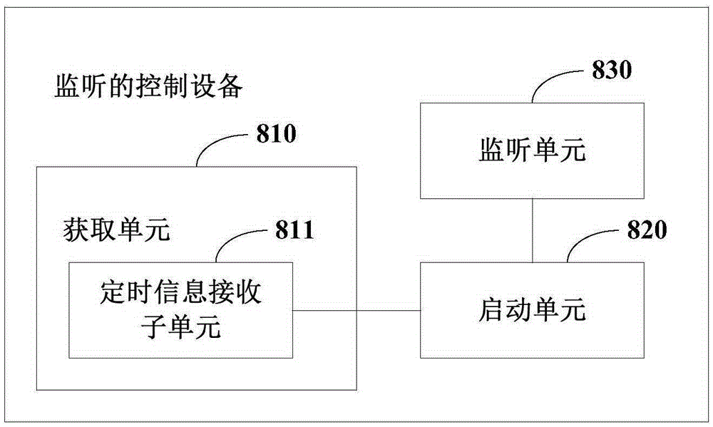
[0106] see Figure 6 , which is a block diagram of the first embodiment of the monitoring control device of the present invention:

[0107] The terminal includes: an acquisition unit 610 , an activation unit 620 and a monitoring unit 630 .

[0108]Wherein, the obtaining unit 610 is configured to obtain a second timer generated according to the first timer indicated by the timing information, the timing information is included in the first message sent by the peer terminal device, and the first timer is used for controlling the peer terminal device to prohibit sending data to the local terminal device within a first timing period.

[0109] The starting unit 620 is configured to start the second timer and enter a dormant state. The starting unit 620 may include at least one of the following units ( Figure 6 not shown): the first starting subunit is used to start the second timer immediately when the acquiring unit 610 acquires the second timer; the second starting subunit is...

no. 2 example

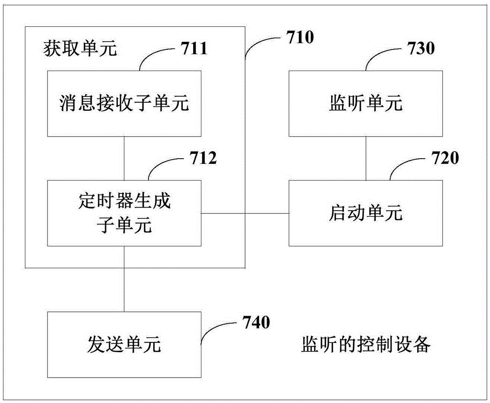
[0111] see Figure 7 , which is a block diagram of the second embodiment of the monitoring control device of the present invention:

[0112] The terminal includes: an acquisition unit 710 , an activation unit 720 , a monitoring unit 730 and a sending unit 740 .

[0113] Wherein, the obtaining unit 710 includes a message receiving subunit 711, configured to receive a first message including timing information sent by the peer terminal device, and the first timer indicated by the timing information is used to control the peer terminal device to It is prohibited to send data to the local terminal device within the first timing period of the first timer; the timer generating subunit 712 is configured to generate a second timing according to the first timing period of the first timer indicated by the timing information device. Among them, the message receiving subunit 711 is specifically configured to receive the first message including timing information transparently transmitte...


PUM


Abstract

The invention discloses a monitoring control method and device. The method includes: a local terminal device acquiring a second timer generated by a first timer which is indicated by timing information included in a first message sent by an opposite-end terminal device and the first timer is used for controlling the opposite-end terminal device to be forbidden to send data to the local terminal device in a first timing period; the local terminal device starting the second timer and entering a dormant state; and the local terminal device ending the dormant state and monitoring the PDCCH when a second timing period of the second timer arrives. In the monitoring control method and device, the local terminal device can be woken up according to the second timer in a targeted way to receive the data transmitted by the opposite-end terminal device. Because the local terminal device does not need to monitor channels blindly, requirements for data transmission are met and at the same time, power consumption of the local terminal device is reduced.

Description

technical field [0001] The invention relates to the technical field of network communication, in particular to a monitoring control method and equipment. Background technique [0002] In a communication system, DRX (Discontinuous Reception, discontinuous reception) can be divided into IDLE (idle state) DRX and ACTIVE (connection state) DRX. UE (UserEquipment, user equipment) is usually in a dormant state when it is in IDLEDRX, but it will set a paging cycle and monitor the paging channel at the arrival of each paging cycle. If it detects paging, it will access the network for communication, otherwise Continue to be in the dormant state; when the UE is in ACTIVEDRX, it is connected to the network, but it can still be dormant according to the preset cycle. According to the length of the cycle, it can be divided into LONGDRX (long DRX) and SHORTDRX (short DRX), and monitor when the cycle arrives PDCCH (PhysicalDownlinkControlChannel, Physical Downlink Control Channel), if sche...

Claims


Application Information

Patent Timeline
Patent Type & Authority Patents(China)
IPC IPC(8): H04L12/24H04L12/26
Inventor 张向东
Owner HUAWEI TECH CO LTD
Why Eureka
Try Eureka