Signal detection method and system

A signal detection and signal technology, applied in wireless communication, electrical components, etc., can solve problems such as user perception drop, interference, signal detection measurement error, etc.

Active Publication Date: 2013-10-23
ULTRAPOWER SOFTWARE
View PDF5 Cites 6 Cited by
  • Summary
  • Abstract
  • Description
  • Claims
  • Application Information

AI Technical Summary

Problems solved by technology

These problems lead to the deterioration of wireless signal quality, serious interference of levels 5 to 7, and significant decline in user perception
[0003] In the traditional method of analyzing interference and coverage of regular hexagonal cell clusters, the boundary and center point of the frame period and slot period are only roughly estimated, resulting in large errors in the measurement of various parameters in signal detection, and even many parameters It cannot be calculated, which greatly limits the scope and degree of e

Method used


Image

  • Signal detection method and system
  • Signal detection method and system
  • Signal detection method and system

Examples


Embodiment Construction

[0054] In order to make the object, technical solution and advantages of the present invention clearer, the implementation manner of the present invention will be further described in detail below in conjunction with the accompanying drawings.

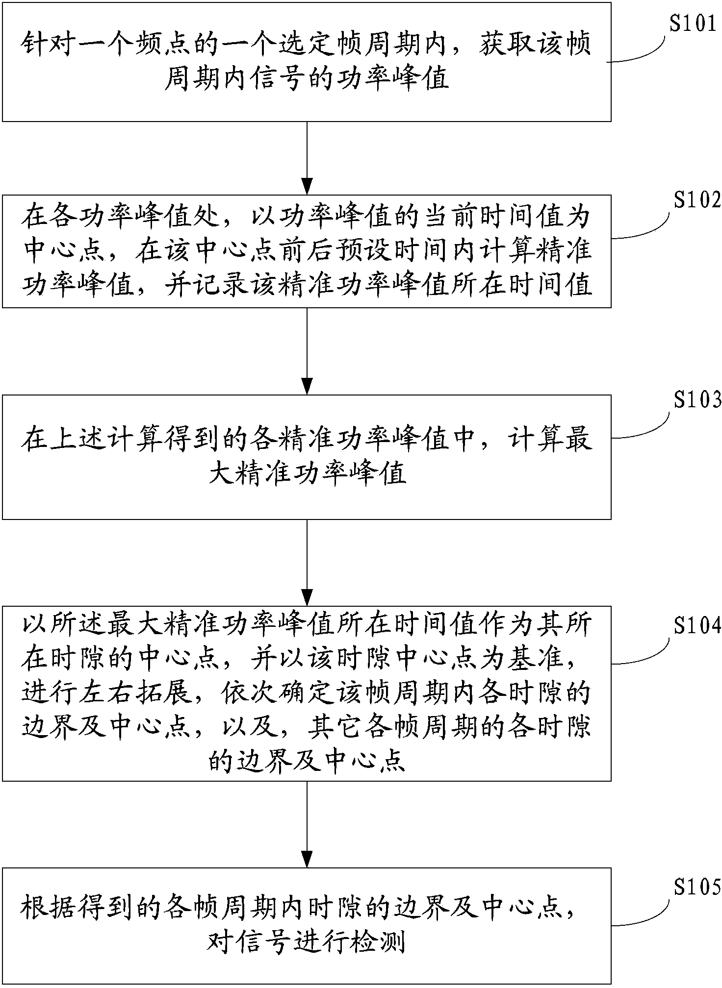
[0055] see figure 1 As shown, the embodiment of the present invention provides a signal detection method, which specifically includes:

[0056] S101: For a selected frame period of a frequency point, acquire a signal power peak value within the frame period.

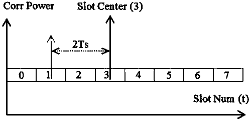
[0057] It should be noted that, in order to determine the precise boundary and center point of each time slot in the embodiment of the present invention, a frame period may be randomly selected to execute step S101.

[0058] At the same time, during the execution of step S101, the power data of all signals within the frame period may also be recorded, so as to analyze the signal power for subsequent steps.

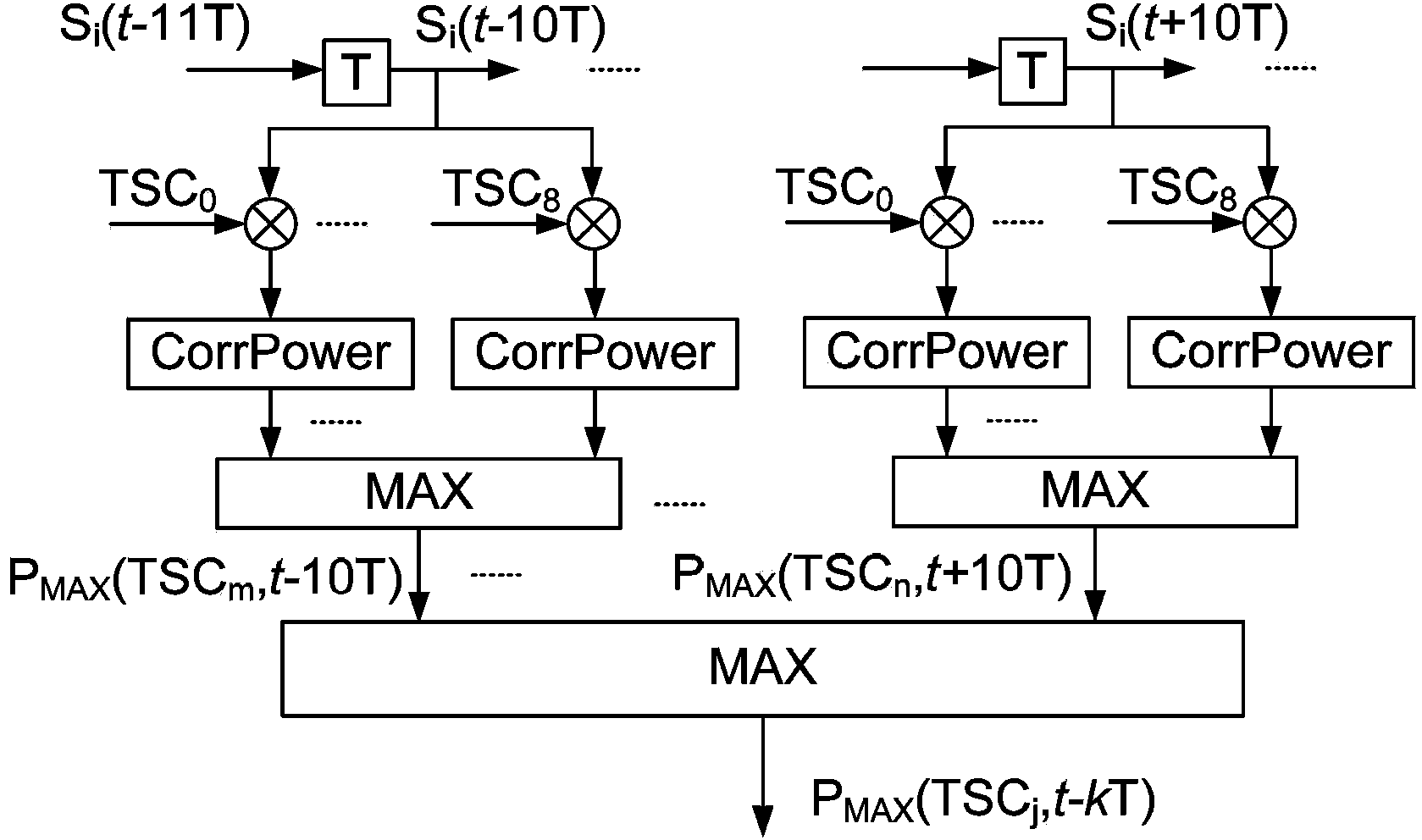
[0059] Specifically, obtaining the peak power of the signal within the f...


PUM


Abstract

The invention discloses a signal detection method and system and relates to the field of mobile communication technologies. The method includes the steps of step 1, obtaining power peak values of signals in a frame period, step 2, computing accurate power peak values and recording time values when the accurate power peak values are located in preset time before and after a center point, wherein the current time value of the power peak values serves as the center point in all power peak values, step 3, computing the maximum accurate power peak value in all the obtained accurate power peak values through computation, step 4, carrying out expansion left and right on a time slot central point to determine boundaries and central points in the frame period and other frame periods, wherein the time value when the maximum accurate power peak value is located serves as the central point of the time slot when the maximum accurate power peak value is located , and step 5, carrying out signal detection according to the boundaries and central points in each frame period. The signal detection method and system provide basis for deeper scientific and accurate qualitative analysis, furthermore, provide more accurate optimized schemes for signal direction, and improve the whole performance of honeycomb wireless networks fundamentally.

Description

technical field [0001] The invention relates to the technical field of mobile communication, in particular to a signal detection method and system. Background technique [0002] With the rapid growth of mobile services, the wireless network load is increasing day by day, and GSM900, DCS1800, and EGSM frequency bands have been put into large-scale applications one after another. While the distance between the base stations of the cellular wireless network is continuously shrinking, the number of high-carrier configuration sites is also increasing rapidly, and the frequency reuse density is continuously increasing. At present, the GSM wireless network of China Mobile Group generally has problems such as excessive overlapping coverage, serious cross-region coverage, a sharp increase in the probability of co-adjacent channel interference, and a significant increase in the noise floor of the wireless network system. These problems lead to the deterioration of wireless signal qua...

Claims


Application Information

Patent Timeline
IPC IPC(8): H04W24/02
Inventor 黄剑锋
Owner ULTRAPOWER SOFTWARE
Why Eureka
Try Eureka