
Level-variable turbocharging system and engine with same

A turbocharger system and turbocharger technology, applied in combustion engines, machines/engines, internal combustion piston engines, etc., can solve the problem of supercharging pressure ratio, acceleration response effect is not very ideal, can not take into account the engine well High and low speed performance, exhaust gas recirculation ratio and limited working condition range, etc., to achieve the effect of large exhaust gas recirculation rate and working condition range, good emission and plateau adaptability, and high boost pressure ratio

Active Publication Date: 2014-03-05
HUNAN TYEN MACHINERY
View PDF5 Cites 5 Cited by
  • Summary
  • Abstract
  • Description
  • Claims
  • Application Information

AI Technical Summary

Problems solved by technology

[0003] On the basis of one-stage turbocharging, a two-stage turbocharging system has appeared on the engine. The current two-stage supercharging system is composed of two large and small turbochargers connected in series or in parallel, although it can improve engine acceleration. , compressor and turbine flow range, supercharging system efficiency, but the degree of improvement is limited, the ratio of exhaust gas recirculation and the range of operating conditions that it can achieve are also limited, and the effects of boost pressure ratio and acceleration response provided are not good. It is very ideal, but it cannot take into account the high and low speed performance of the engine, so that the low speed, medium and low speed and small load, medium and small load performance and high speed performance of the engine are not very ideal. In practice, it is difficult to achieve stable performance on plateaus and plains.

Method used


Image

  • Level-variable turbocharging system and engine with same
  • Level-variable turbocharging system and engine with same
  • Level-variable turbocharging system and engine with same

Examples


Embodiment 1

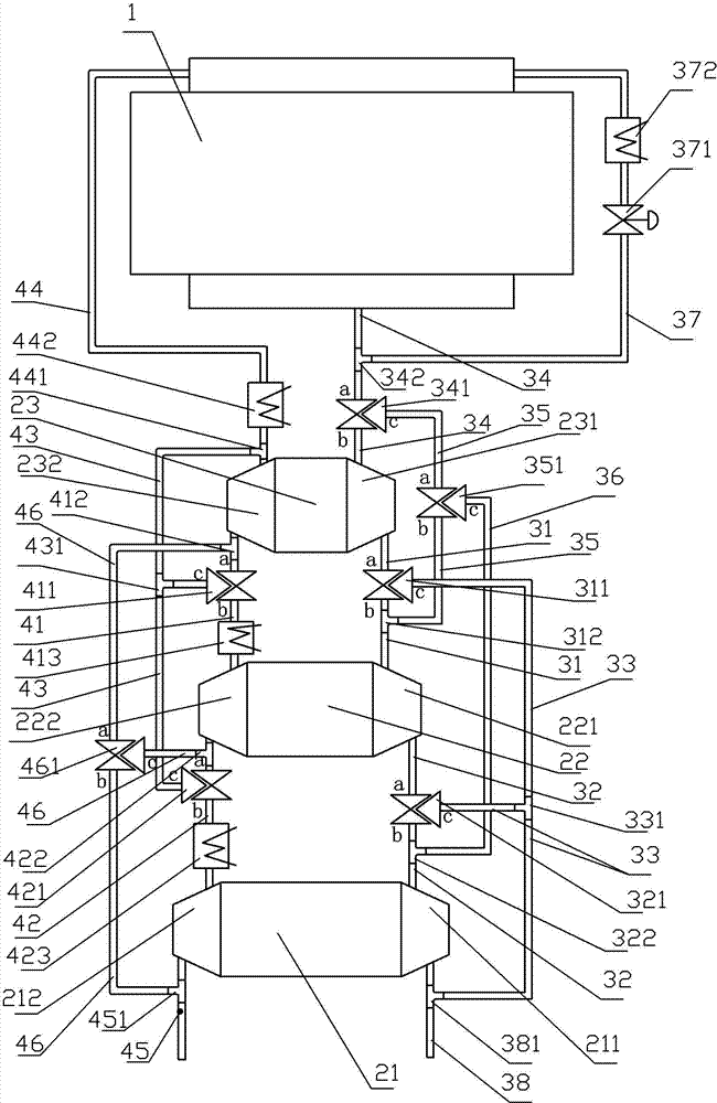
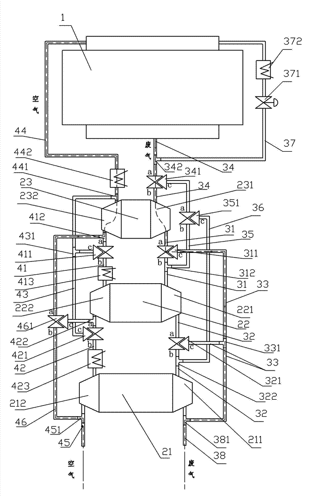
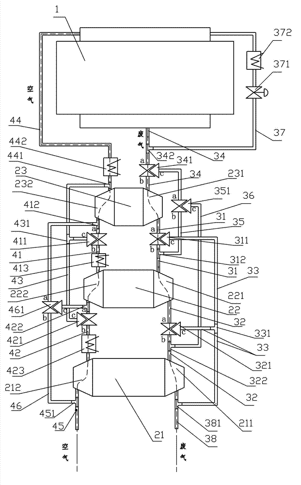
[0025] Such as figure 1 Shown: an engine with a variable-stage turbocharging system, which includes an engine 1 and a variable-stage turbocharging system; the engine 1 includes an engine mechanical assembly and an engine electronic control unit; the variable-stage turbocharging system includes Large turbocharger 21, medium turbocharger 22, small turbocharger 23 three turbochargers with unequal flows (the described large, medium and small are relative, not absolute values, are In order to distinguish the unequal flow of the three turbochargers; the unequal flow means that at the same speed, the intake air volume of the turbocharger is not equal, and the macroscopic structure generally shows that the blade diameters of the turbocharger are not equal , that is, the flow rate of the large turbocharger 21 is greater than that of the medium turbocharger 22 (compared at the same speed, generally at the rated flow rate), and the flow rate of the medium turbocharger 22 is greater than ...


PUM


Abstract

An engine with a level-variable turbocharging system comprises an engine body (1) and the level-variable turbocharging system, wherein the engine body (1) comprises an engine mechanical assembly and an engine electric control unit; the level-variable turbocharging system comprises a large turbocharger (21), a middle turbocharger (22) and a small turbocharger (23) which are different in flow, each of the turbochargers comprises a turbine and an air compressor which form a network with an air pipe through a tee joint (312), a tee joint (322), a tee joint (331), a tee joint (342), a tee joint (381), a tee joint (412), a tee joint (422), a tee joint (441), a tee joint (451), a three-way valve (311), a three-way valve (321), a three-way valve (341), a three-way valve (351), a three-way valve (411), a three-way valve (421) and a three-way valve (461), and connected with the engine body (1).

Description

technical field [0001] The invention relates to engine and engine turbocharger technology, in particular to a variable-stage turbocharger system and an engine with a variable-stage turbocharger system. Background technique [0002] In order to reduce greenhouse gas emissions, the state vigorously advocates energy conservation and emission reduction. Engine exhaust emissions have become an important source of greenhouse gas emissions. Engine exhaust emissions are mainly automobile engine exhaust emissions, because in recent years, the production and sales of automobiles have risen sharply. On the other hand, for automobile engines, users are increasingly demanding that the engine has a relatively large power per liter, good acceleration, and a good driving experience. In order to solve the problems of environmental protection and power of the above-mentioned engines (that is, the environmental protection performance and power performance of the engine), people have added a ...

Claims


Application Information

Patent Timeline
Patent Type & Authority Applications(China)
IPC IPC(8): F02B37/007F02B37/013F02B37/12
CPCY02T10/144Y02T10/12
Inventor 周成尧刘科仕刘艳东张城陈章科张华达刘磊杨迪
Owner HUNAN TYEN MACHINERY
Learn More