Supercharge Your Innovation With Domain-Expert AI Agents!

Glass bottle forming method

A molding method and glass bottle technology, applied in blowing-blowing glass forming machines, glass production, blowing heads, etc., can solve the problem of difficult air discharge and achieve the effect of not being prone to defects

Inactive Publication Date: 2013-10-23
TOYO GLASS CO LTD
View PDF7 Cites 2 Cited by
  • Summary
  • Abstract
  • Description
  • Claims
  • Application Information

AI Technical Summary

Problems solved by technology

[0010] As described in Patent Document 1, if a vent hole is formed on the top of the plunger, the air in the cavity will indeed be easily discharged, but as Image 6 As shown in the air 10, the air on the lower side than the top of the plunger is still difficult to escape

Method used


Image

  • Glass bottle forming method
  • Glass bottle forming method
  • Glass bottle forming method

Examples


Embodiment Construction

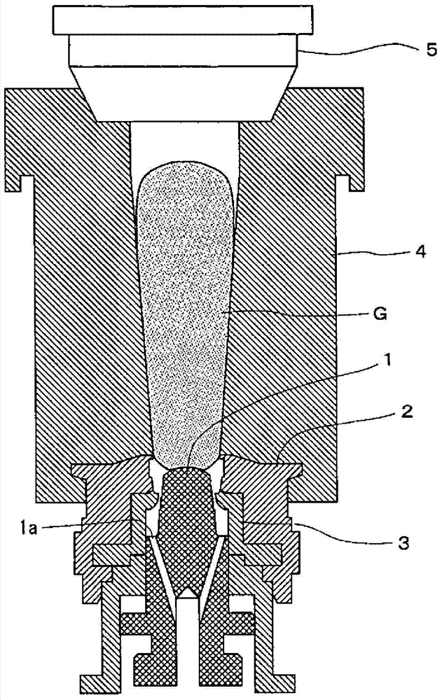
[0026] figure 1 It is a figure in which the glass material G is thrown into the preform 4 through the hopper 5 in the glass bottle molding method of this invention. The plunger 1 is inserted into the central opening of the die 2 and the guide ring 3 installed in the die, and the plunger 1 is driven in the vertical direction by a driving mechanism (not shown) such as an air cylinder. A prefabricated mold 4 is provided on the upper part of the die 2 .

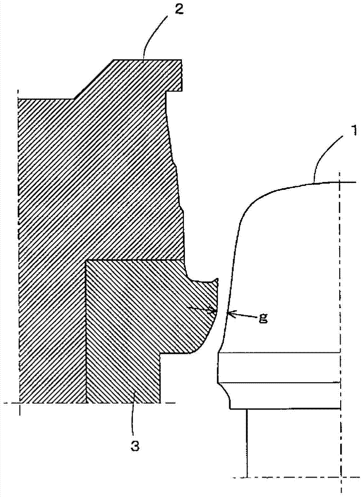
[0027] When the glass blank G is dropped into the prefabricated mold 4, the position of the plunger 1 is Figure 4 The normal position drops about 6mm figure 2 At this time, the minimum gap g between the side of the plunger 1 and the inner surface of the guide ring 3 is 0.1-1.1mm.

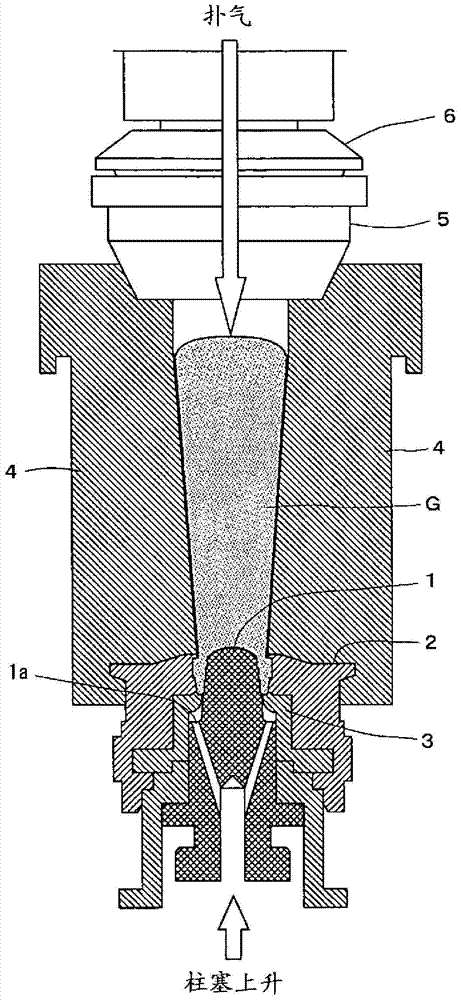
[0028] After the input of the glass blank is completed, if image 3 As shown, the baffle plate 6 descends above the funnel 5, and the compressed air is supplied from the baffle plate to the prefabricated mold 4 to blow air. Plunger 1 basically ...


PUM


Abstract

This glass bottle forming method reduces the occurrence of defective products by facilitating the removal of air from inside a cavity of a blank mold when a gob has been introduced such that air does not remain in the cavity when settle blowing has been performed. The position of a plunger when the introducing a gob into the blank mold is set lower than the regular position of the plunger when forming the parison opening. A prescribed minimal gap g is provided between the plunger and a guide ring, and when the settle blowing is performed and the plunger is raised up to the regular position, no air is left in the cavity when settle blowing has been performed, thus decreasing the occurrence of defective products.

Description

technical field [0001] The invention relates to a method of manufacturing glass bottles according to the so-called blow and blow method. Background technique [0002] based on Figure 7 The outline of the process of molding glass bottles by the blow-blow method is explained. Figure 7 In (a)-(c), the parison P which is a semi-finished product is manufactured from the glass material G (block of molten glass) using the preform 4. Figure 7 In (a), the glass blank G is put into the prefabricated mold 4 through the funnel 5, Figure 7 In (b), pressurize (puff) with compressed air from above through the baffle plate 6, put the glass into the die 2 under the preform 4, and make the mouth. Figure 7 In (c), the plunger 1 is lowered, air is blown into the cavity (back blowing), and the parison P is molded by the preform 4 and the upper baffle 6 . Figure 7 In (d), the parison P is moved to the final mold 7 using the mechanical device 9 (turning device). In this case, the prefabricate...

Claims


Application Information

Patent Timeline
IPC IPC(8): C03B9/14
CPCC03B9/36C03B9/3645C03B9/3654Y02P40/57
Inventor 林达雄大屋祐一
Owner TOYO GLASS CO LTD
Features
  • R&D
  • Intellectual Property
  • Life Sciences
  • Materials
  • Tech Scout
  • Unparalleled Data Quality
  • Higher Quality Content
  • 60% Fewer Hallucinations
Learn More