Blow-moulding machine with base cooling in the stabilisation phase

An internal, time-segmented technology, applied in the direction of household appliances, hollow objects, other household appliances, etc.

Active Publication Date: 2013-10-30
KRONES AG
View PDF4 Cites 0 Cited by
  • Summary
  • Abstract
  • Description
  • Claims
  • Application Information

AI Technical Summary

Problems solved by technology

The disadvantage of post-cooling the base by water is that the container is then

Method used


Image

  • Blow-moulding machine with base cooling in the stabilisation phase
  • Blow-moulding machine with base cooling in the stabilisation phase
  • Blow-moulding machine with base cooling in the stabilisation phase

Examples


Embodiment Construction

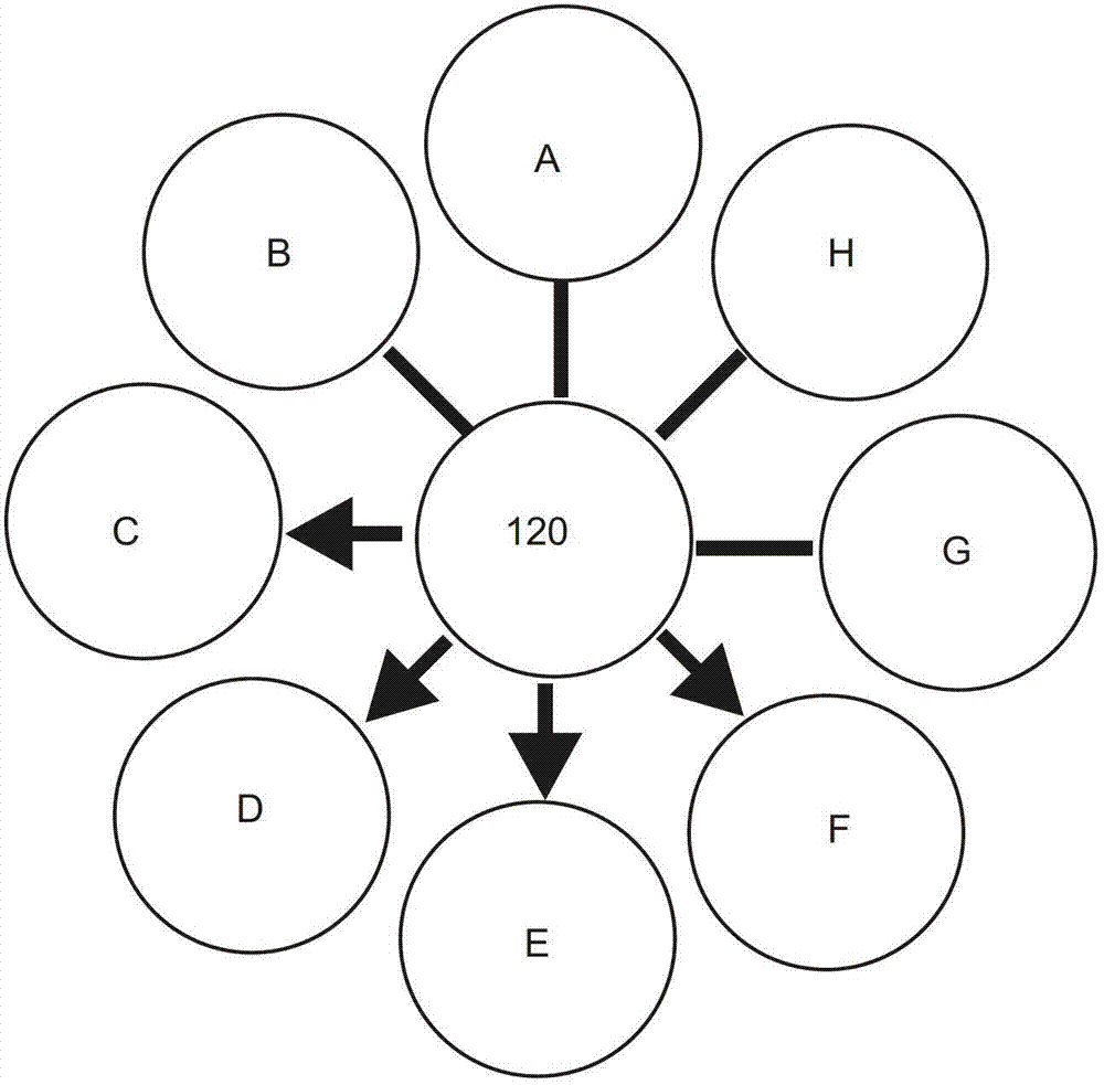
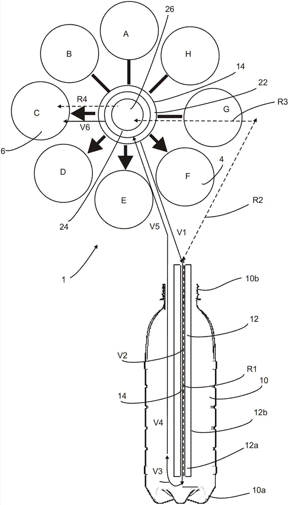
[0083] figure 1 is a rough schematic diagram of the sequence of methods according to the prior art. In this case, a blow molding machine with eight stations A-H is shown roughly schematically. In this case (also in figure 2 ), the letters indicate the following states of the method:

[0084] A: Open the blow mold;

[0085] B: transfer of the plastic preform into the blow mold;

[0086] C: forming a container - especially by applying pressure to it;

[0087] D: The container is complete and held under pressure;

[0088] E: The container is complete and held under pressure;

[0089] F: The container is complete and held under pressure;

[0090] G: The container is lowered (released from pressure);

[0091] H: Transfer the finished container out of the blow mold.


PUM


Abstract

The invention relates to a blow molding machine for producing plastic containers (10). A container be expanded on the one hand is supplied with blown air by a first gas supply device (22) or on the other hand by a second gas supply means (24) is supplied with blown air during a blow molding process. During this process, a base of the container is cooled in addition.

Description

technical field [0001] The present invention relates to a device and a method for producing plastic containers, in particular to a device and a method for forming plastic preforms into plastic containers. Background technique [0002] Devices and methods of this type are already known from the prior art. Usually the plastic pre-forms are first heated by means of a furnace, and these plastic pre-forms heated in this way are subsequently shaped into containers in blow molding machines, in particular stretch blow molding machines, by blowing air acting on them. In this case, this forming process is a relatively complex process and can usually be divided into several partial steps. In this way, the container is inflated by the preliminary blowing pressure, and then the final blowing pressure is usually applied, and the container finally expanded in this way is maintained at the pressure for a predetermined period of time, so that the deformed state can be stabilized. [0003] ...

Claims


Application Information

Patent Timeline
IPC IPC(8): B29C49/30B29C49/64B29L22/00
CPCB29C2049/5841B29C49/12B29C2049/6692B29C49/58B29C2049/1228B29C49/783B29C49/18B29C49/36B29C49/66B29C49/64B29C49/1212B29C2049/7832
Inventor 彼得·克纳普
Owner KRONES AG
Why Eureka
Try Eureka