Drive trains for motor vehicles

A technology of drive train and motor vehicle, applied in the field of drive train for motor vehicles, which can solve the problems of unfavorable service life, uncomfortable startup and shutdown of internal combustion engines, etc.

Inactive Publication Date: 2017-12-29
SCHAEFFLER TECH AG & CO KG
View PDF1 Cites 0 Cited by
  • Summary
  • Abstract
  • Description
  • Claims
  • Application Information

AI Technical Summary

Problems solved by technology

Frequent starting and stopping of the internal combustion engine is neither comfortable nor favorable for the service life of the components of the drive train of the motor vehicle

Method used


Image

  • Drive trains for motor vehicles
  • Drive trains for motor vehicles
  • Drive trains for motor vehicles

Examples


Embodiment Construction

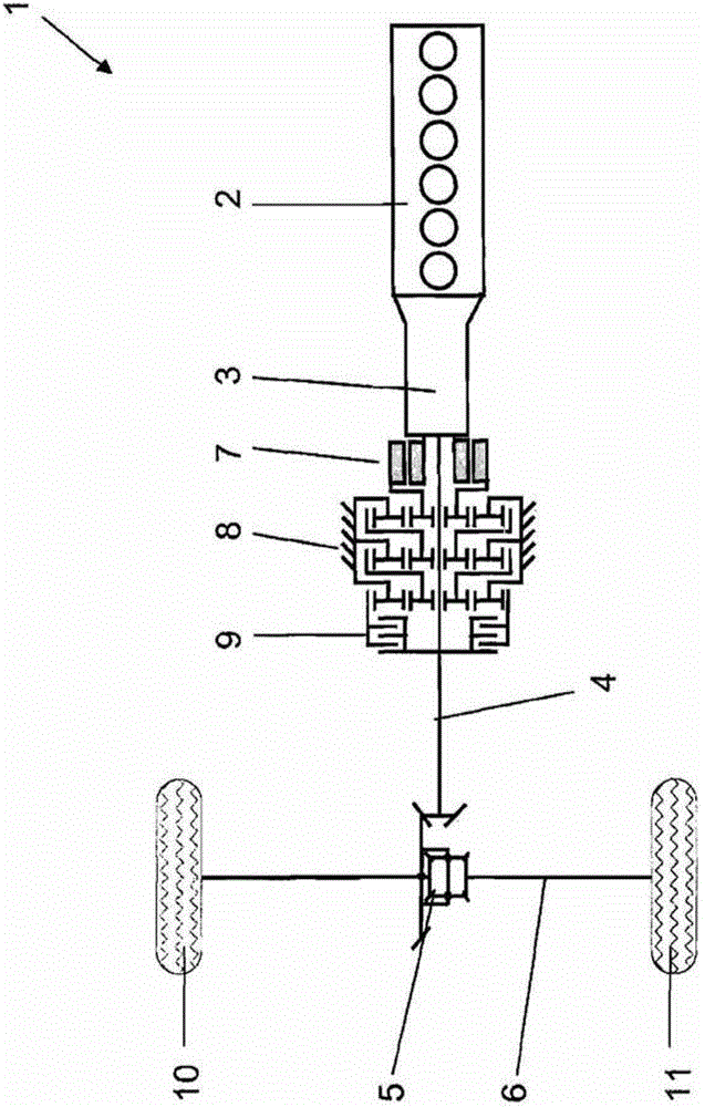
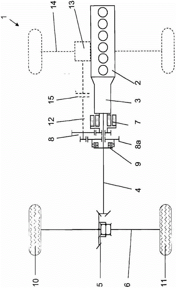
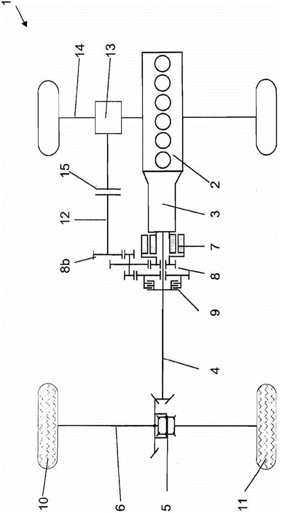
[0023] figure 1 A drive train 1 is shown, which is used, for example, in a motor vehicle. Here, a main prime mover 2 in the form of an internal combustion engine is connected to a main transmission 3 with a transmission output shaft 4 , which leads to a first axle differential 5 arranged on a drive shaft 6 of the motor vehicle. Based on this configuration, the main prime mover 2 drives the wheels 10 , 11 connected to said first drive shaft 6 .

[0024] The electric motor 7 designed as an outer rotor mounted as an auxiliary prime mover is connected to an auxiliary transmission 8 , which in turn is designed as a single-stage or multi-stage planetary transmission. The last transmission stage 8 a of the auxiliary transmission 8 is connected here to a coupling element 9 in the form of a clutch, which connects the electric motor 7 to the transmission output shaft 4 or disconnects this connection. The electric motor 7 and the auxiliary transmission 8 are arranged as a compact unit ...


PUM


Abstract

The powertrain (1) has a main motor (2) for driving wheels (10, 11) of a drive axle (6) over a main gear box (3), which is connected with a differential (5) over a transmission output shaft (4), where the differential is mounted on the drive axle. An auxiliary motor (7) is connected to the output shaft over a single-stage auxiliary gear box (8) in order to drive the motor car with low speed. The auxiliary motor is formed as an electromotor and arranged coaxial to the output shaft. The auxiliary gear box designed as spur gear or planetary gear and arranged downstream to the auxiliary motor. The main motor is designed as a front longitudinal motor and connected in form of a combustion engine with the main gear box.

Description

technical field [0001] The invention relates to a drive train for a motor vehicle, comprising a main prime mover and an auxiliary prime mover, the main prime mover driving the wheels of the drive shaft of the motor vehicle through a main transmission, the main transmission being supported on the drive shaft through a transmission output shaft The auxiliary prime mover is connected to the transmission output shaft through the auxiliary transmission for driving the motor vehicle at low speeds. Background technique [0002] Document WO 00 / 20243 A1 discloses motor vehicles in which the electric motor is connected within the drive train of the motor vehicle via a transmission. It is also known that the electric motor is arranged axially parallel to the transmission output shaft and is connected to the transmission output shaft via an auxiliary transmission and a coupling element, preferably a freewheel. Alternatively, the coupling element can also be designed as a clutch. The c...

Claims


Application Information

Patent Timeline
Patent Type & Authority Patents(China)
IPC IPC(8): B60K17/16B60K17/28
CPCB60K6/26B60K6/52B60K2006/4808B60K2006/4833Y02T10/62
Inventor M·梅茨U·潘瑟
Owner SCHAEFFLER TECH AG & CO KG
Why Eureka
Try Eureka