Tensioner core and tensioner and diverter with the same

A tensioner, steering gear technology, applied in transmission, belt/chain/gear, mechanical equipment, etc., can solve problems such as hydraulic oil leakage, improve stability, be less prone to vibration and abnormal noise, and improve work performance. Effect

Active Publication Date: 2015-11-25
BYD CO LTD
View PDF8 Cites 0 Cited by
  • Summary
  • Abstract
  • Description
  • Claims
  • Application Information

AI Technical Summary

Problems solved by technology

[0003] The first purpose of the present invention is to solve the problem that the hydraulic oil of the tensioner is prone to leakage and oil circuit compensation is required, and a tensioner with adjustable tension and without oil circuit compensation structure is specially designed Core

Method used


Image

  • Tensioner core and tensioner and diverter with the same
  • Tensioner core and tensioner and diverter with the same
  • Tensioner core and tensioner and diverter with the same

Examples


Embodiment Construction

[0032] In order to make the technical problems, technical solutions and beneficial effects solved by the present invention clearer, the present invention will be further described in detail below in conjunction with the accompanying drawings and embodiments. It should be understood that the specific embodiments described here are only used to explain the present invention, not to limit the present invention.

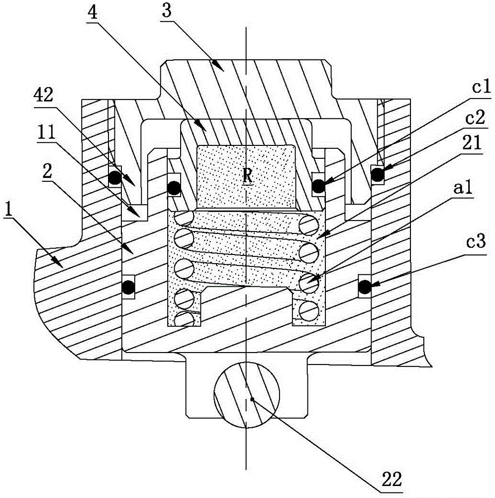
[0033] figure 2It is a sectional view of the first embodiment of a tensioner core of the present invention. The tensioner core is installed on the housing 1, and the tensioner core includes: a plunger 2, which is slidably inserted in the plunger receiving hole 11 of the housing 1 and one end thereof extends from the plunger receiving hole 11 The plunger 2 has a cylindrical opening facing the hollow portion 21 of the plunger receiving hole 11; one end of the first spring a1 extends into the hollow portion 21 of the plunger 2 and extends toward the plunger 2. Apply forc...


PUM


Abstract

A tensioner core body is arranged on a shell, comprises a plunger and a first spring, and further comprises an adjusting nut and a supporting sleeve, wherein the plunger is slidingly inserted in a plunger accommodating hole in the shell, one end of the plunger extends out from the plunger accommodating hole, and the plunger is provided with a cylindrical hollow portion with the opening facing the longitudinal direction of the plunger accommodating hole; one end of the first spring extends into the hollow portion of the plunger and applies force on the plunger towards the direction, where the plunger extends out of the plunger accommodating hole; the adjusting nut is arranged in the plunger accommodating hole and is far away from the end of the plunger, which extends out form the plunger accommodating hole, and the adjusting screw is threadedly connected with the plunger accommodating hole; the supporting sleeve supports and abuts against the adjusting nut through the first spring. A sealing hydraulic oil chamber with oil pressure is formed between the supporting sleeve and the hollow portion of the plunger, and the plunger can move axially along the plunger accommodating hole relative to the supporting sleeve. The tensioner core body has superior performance and can well meet work requirements of ring-shaped soft members.

Description

technical field [0001] The invention relates to a tensioner applied to an annular flexible member for transmission to keep the annular flexible member in a certain tension state. Background technique [0002] At present, the reduction mechanism often used in electric power steering (REPS) is synchronous belt transmission, which is mainly composed of motor, small pulley, synchronous belt, large pulley and ball screw pair, and the motor drives the small pulley to rotate. Driven by a synchronous belt, power is provided for the steering gear. The above-mentioned reduction mechanism adopts synchronous belt transmission, which has high requirements on the processing and assembly precision of the parts. The synchronous belt transmission has stricter installation center distance, and the center distance is too small, resulting in a small tension of the synchronous belt and loosening during belt transmission. Or slipping phenomenon, affecting the transmission efficiency and producin...

Claims


Application Information

Patent Timeline
Patent Type & Authority Patents(China)
IPC IPC(8): F16H7/08F16H7/02
Inventor 张静刘佳佳
Owner BYD CO LTD
Why Eureka
Try Eureka