Non-contact optical fiber device and method for measuring flows

A non-contact, optical fiber measurement technology, applied in measuring devices, optical radiation measurement, fluid flow detection by measuring pressure difference, etc., can solve the problems of destroying the flow field of the pipe flow, inconvenient installation and disassembly, damage, etc., to save energy , the effect of simple structure

Inactive Publication Date: 2013-10-30
CHINA PETROLEUM & CHEM CORP +1
View PDF8 Cites 9 Cited by
  • Summary
  • Abstract
  • Description
  • Claims
  • Application Information

AI Technical Summary

Problems solved by technology

The measurement methods are nothing more than two categories: contact and non-contact. The existing contact and non-contact measurement methods, such as the throttling part of the throttling flowmeter, the turbine of the turbine flowmeter, and the electrode of the electromagnetic flowmeter etc. This type of flowmeter has contributed to flow measurement, especially to the flow measurement of oil production and transmission, but it also has the following shortcomings or deficiencies: ① the sensing element of the flow meter is in contact with the measured fluid, and The detection element in contact with the fluid will not only cause pressure loss, but also destroy the original flow field of the pipe flow; ② Generally, it is permanently connected to the system and can only measure the flow of a fixed part; ③ The sensing element of the flow meter itself is easily affected by the fluid Impact, wear, and even corrosion; ④Inconvenient installation and disassembly, easy to cause leakage and damage during installation and disassembly

Method used


Image

  • Non-contact optical fiber device and method for measuring flows
  • Non-contact optical fiber device and method for measuring flows
  • Non-contact optical fiber device and method for measuring flows

Examples


Embodiment Construction

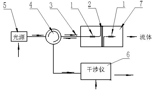
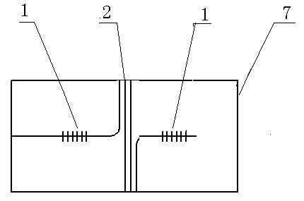
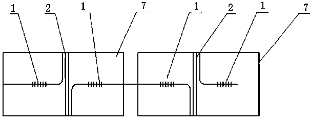
[0021] refer to Figure 1-Figure 5 , a device and method for non-contact fiber optic flow measurement, the device includes a grating 1, a sensing fiber 2, an optical fiber 3, a circulator 4, a light source 5, an interferometer 6, and a pipeline 7. The sensing optical fiber 2 is installed on the pipeline 7, one end of the sensing optical fiber 2 is connected to the grating 1, the optical fiber 3, the circulator 4, and the light source 5 in sequence, and the other end is connected to the grating 1, and the interferometer 6 is connected to the circulator 4. connect.

[0022] The interferometer 6 communicates with the light source 5 through the circulator 4 , and communicates with the optical fiber 3 , the grating 1 and the sensing optical fiber 2 through the output end of the circulator 4 . One end of the sensing fiber 2 is connected to the grating 1, and the other end is connected to the grating 1 or the reflector.

[0023] Non-contact fiber optic flow measuring device The met...


PUM


Abstract

The invention provides a non-contact optical fiber device and method for measuring flows. The device comprises a sensing fiber mounted in a pipeline. One end of the sensing fiber is connected with a grating, an optical fiber, a circulator and a light source sequentially, and the other end is connected with the grating, an interferometer and the circulator. The method includes connecting the grating to two sides of the sensing fiber to form a sensing unit, allowing light emitted from the light source to enter the sensing unit from the front end, converting monitoring vibration acceleration into monitoring optical phase by the grating interferometric technique, performing demodulation processing on phase information by the phase carrier technique PGC (programmed gain control), and realizing non-contact flow monitoring. The device is free of contacting with fluid, interfering with the flow field and electrical measurement, safe and reliable, high in adaptability, and free of being interfered by electromagnet; continuous remote measurement is realized, influences by light fluctuation and temperature changes are eliminated, throttle pressure loss rarely occurs, energy is saved, flows of corrosive fluids can be measured, multi-point measurement can be realized, and the device can be applied in measurement processes with various flows.

Description

technical field [0001] The invention relates to an optical fiber flowmeter in the technical field of optoelectronic measurement, in particular to a device and method for non-contact optical fiber flow measurement. Background technique [0002] Flow measurement is an important basis for modern industrial production, especially in the petrochemical field. Flow measurement can provide extremely important information for oil and gas pipeline detection, dynamic monitoring of production wells, and oil production and transmission characteristics in complex environments such as anti-corrosion, explosion-proof, high temperature and high pressure. parameters. The measurement methods are nothing more than two categories: contact and non-contact. The existing contact and non-contact measurement methods, such as the throttling part of the throttling flowmeter, the turbine of the turbine flowmeter, and the electrode of the electromagnetic flowmeter etc. This type of flowmeter has contr...

Claims


Application Information

Patent Timeline
Patent Type & Authority Applications(China)
IPC IPC(8): G01F1/36G01J9/00
Inventor 孙宝全刘小会张国玉赵文安杨斌尚盈许玲玲姜广彬张福涛郭林园
Owner CHINA PETROLEUM & CHEM CORP
Why Eureka
Try Eureka