Impedance measurement method of three-phase alternating current system

A three-phase AC and impedance measurement technology, which is applied in the direction of measuring devices, measuring electrical variables, measuring resistance/reactance/impedance, etc., can solve problems such as complex structure of the measurement system, and achieve the effect of simple test platform and easy data processing steps

Inactive Publication Date: 2013-10-30
XI AN JIAOTONG UNIV
View PDF5 Cites 14 Cited by
  • Summary
  • Abstract
  • Description
  • Claims
  • Application Information

AI Technical Summary

Problems solved by technology

However, the obvious disadvantage of this method is the need to use three injection sources, which complicates the measurement system structure

Method used


Image

  • Impedance measurement method of three-phase alternating current system
  • Impedance measurement method of three-phase alternating current system
  • Impedance measurement method of three-phase alternating current system

Examples


Embodiment Construction

[0039] Below in conjunction with accompanying drawing, the present invention is described in further detail:

[0040] see Figure 1 to Figure 4 Shown, a kind of three-phase AC system impedance measuring method of the present invention comprises the following steps:

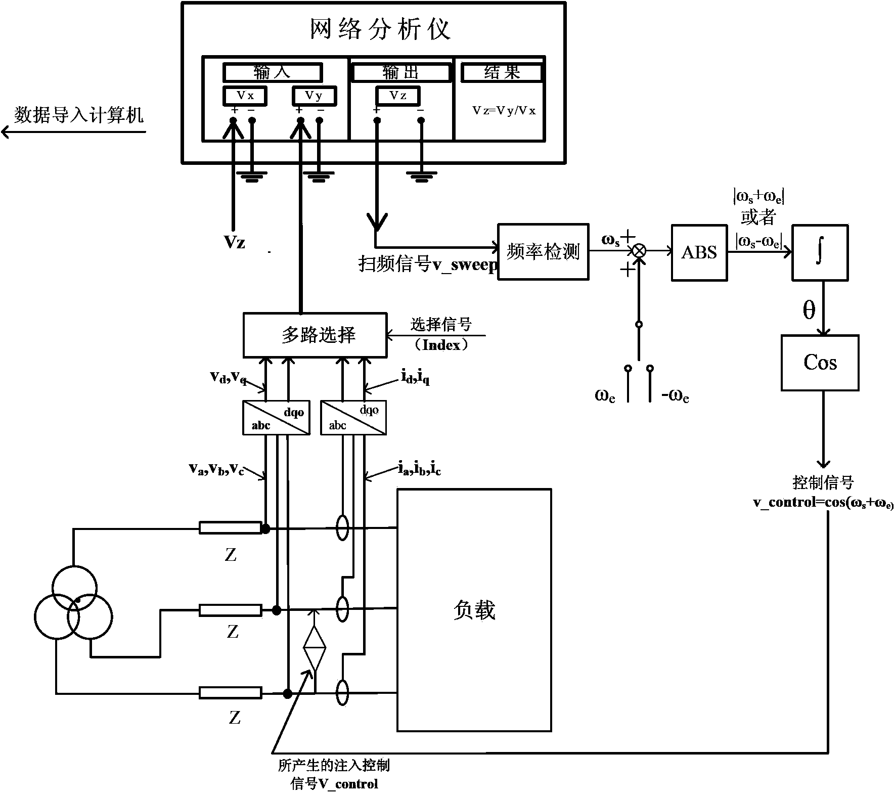
[0041] 1. Acquisition of experimental data

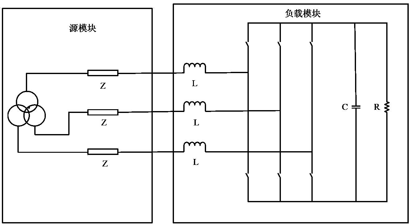
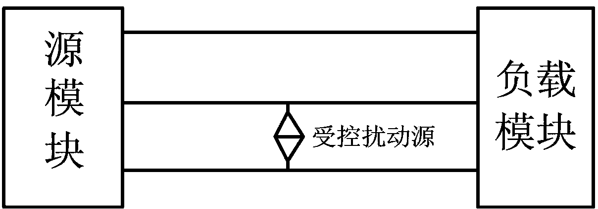
[0042] refer to figure 1 , using a PWM rectifier as an example system to illustrate the specific implementation of the present invention. Such as figure 1 As mentioned above, the three-phase AC system is divided into two parts according to whether it can work independently: a source module and a load module. The boundary point between the two modules is the impedance measurement point. In order to simplify the explanation process, the system under test is now used figure 2 The block diagram shown shows.

[0043] refer to figure 2 , between the two phases b and c at the boundary between the system source module and the load module, a controlled current disturba...


PUM


Abstract

The invention provides an impedance measurement method of a three-phase alternating current system. The impedance measurement method of the three-phase alternating current system includes the following steps that a frequency sweeping signal sent by the output end of a network analyzing instrument is linked with a frequency detecting link, and the real-time frequency of the frequency sweeping signal is obtained through the frequency detecting link; the real-time frequency obtained by the frequency detecting link subtracts or adds a synchronizing frequency according to the measuring step. After the frequency is processed and obtained through the mentioned steps, an angle changing along with variation of the frequency is obtained through an integration element and consequentially, a sinusoidal signal is further generated and injected into a detected system. A voltage and current signal of a boundary of a system source module and a loading module is collected to carry out dq conversion. The converted signals are sequentially returned to the network analyzing instrument through a multiplexer. Two sets of voltage and current signals which are eight in total are obtained by the network analyzing instrument and used for setting up equation sets, the equation sets are combined for concluding a solution and then, the impedance of the detected system can be obtained. The set-up testing system is simple in structure and late-stage data are easy to process.

Description

【Technical field】 [0001] The invention relates to the technical field of power electronics, in particular to an impedance measurement method for a three-phase AC system. 【technical background】 [0002] As power electronics technology penetrates more and more into the production and processing of electrical energy, we have the ability to control the flow of power and improve the quality of delivered electrical energy. However, power electronic converters are nonlinear, and their dynamic performance is coupled to the source and load to which they are connected. Therefore, in order to provide a stable output, many power electronic systems need to be controlled. This kind of control brings some new risks that are not found in the power system, among which are stability problems. [0003] The power electronic converter with constant power load characteristics presents negative impedance characteristics at its input end, which may lead to system instability. Large power grids c...

Claims


Application Information

Patent Timeline
IPC IPC(8): G01R27/08
Inventor 刘进军包维瀚刘增赵亚林侯雪煜
Owner XI AN JIAOTONG UNIV
Why Eureka
Try Eureka