RRU antenna calibration method, apparatus and system
A technology for antenna calibration and calibration coefficients, applied in diversity/multi-antenna systems, space transmit diversity, etc., can solve problems such as difficult to guarantee accuracy, dependence on accuracy, and occupying air interface resources, achieving high accuracy and ensuring reciprocity , The effect of saving air interface resources
Active Publication Date: 2013-10-30
CHINA MOBILE COMM GRP CO LTD
4 Cites 16 Cited by
AI-Extracted Technical Summary
Problems solved by technology
This solution requires the UE to feed back inter-cell information, and the accuracy of the calibration coefficient calculation is strongly dependent on the amount of feedback, and the accuracy is difficult to gu...
Method used
Above-mentioned RRU antenna calibration device embodiment, by calculating the compensation coefficient of each antenna according to the calibration coefficient between the RRU and the calibration coefficient in the RRU, the calibration of the antennas between the multiple RRUs is realized, so that the ratios of the transceiver channels of all the antennas of the base station are consistent, Guarantee the reciprocity of the uplink and downlink channels of the TDD system, with higher accuracy, less equipment improvement, cost savings, and air interface resources savings.
As shown in Figure 11, the RRU antenna calibration system of the present invention comprises: BBU, a plurality of RRUs and corresponding antenna thereof, wherein the RRU antenna calibration equipment is located in the RRU, and the transceiver channel of the RRU antenna and the calibration port passes through the RRU antenna calibration equipment Connect with BBU. In this embodiment, a splitter combiner is provided between the calibration port and the antenna, and the splitter combiner is located in the RRU, and the splitter combiners of the calibration ports of each RRU are connected by cables, and the RRUs of each RRU The antenna calibration equipment is connected by cables. The calibration port of each RRU transmits the calibration signal through the cable, and sends the received calibration signal to the RRU antenna calibration device. The RRU antenna calibration device corresponding to the reference calibration port collects these signals, and obtains the transmission and reception of other calibration ports after calculation. The calibration coefficient of the channel, and send the compensation coefficient to the RRU antenna calibration equipment of other calibration ports. The antenna and the calibration port in the RRU send the transmitted and received calibration signals to the RRU antenna calibration device, and the RRU antenna calibration device obtains the calibration coefficient for the antenna in the RRU after calculation. The RRU antenna calibration device calculates the compensation coefficients for each antenna transceiver channel according to the RRU inter-RRU calibration coefficient and the RRU internal calibration coefficient, and compensates each antenna transceiver channel to achieve a consistent ratio of antenna transceiver channels.
The RRU antenna calibration method of above-described embodiment, through the connection of RRU calibration port side or the connection of antenna side, receive and send calibration signal, at first the calibration port of each RRU is calibrated; Reuse calibration port to carry out to the antenna in RRU Calibration, so as to realize the calibration of the antennas between multiple RRUs, so that the ratio of the transmitting and receiving channels of all the antennas of the base station is consistent, ensuring the reciprocity of the uplink and downlink channels of the TDD system, with high accuracy and small improvement to the equipment, saving costs and saving air interface resources.
The RRU antenna calibration system of the present invention receives and sends ca...
Abstract
The invention discloses an RRU antenna calibration method, an apparatus and a system. The method comprises the steps of calculating a corresponding calibration coefficient among RRUs to each calibration port according to different RRU calibration ports through calibration signals in interconnected transmission; calculating a corresponding calibration coefficient in a RRU to each antenna in the RRU according to different antennas in the RRUs and the calibration signals transmitted by the calibration ports; and calibrating antenna transmitting channels and antenna receiving channels according to the calibration coefficients among the RRUs and the calibration coefficients in the RRUs so that the proportions of the antenna transmitting channels and the antenna receiving channels are same. The RRU antenna calibration method, the apparatus and the system calibrate different RRU calibration ports through interconnection among the RRUs or side connection of the antennas, and then calibrate the antennas in the RRUs by using the calibration ports, thereby enabling the calibration of the antennas among the RRUs and guaranteeing reciprocity of uplink and downlink channels of a TDD system with high accuracy, less improvement on equipment and lower cost.
Application Domain
Spatial transmit diversity
Technology Topic
Antenna calibrationPhysics +2
Image
Examples
- Experimental program(2)
Example Embodiment
[0061] Method embodiment one
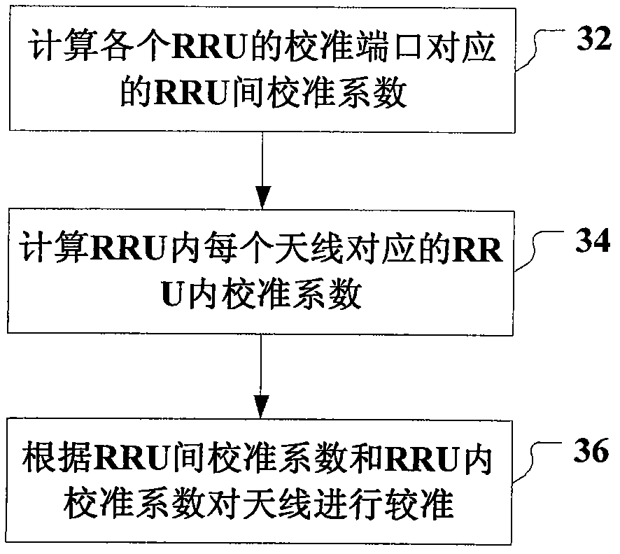
[0062] Such as image 3 As shown, the embodiment of the RRU antenna calibration method of the present invention includes:
[0063] Step 302: Calculate the inter-RRU calibration coefficient corresponding to the calibration port of each RRU according to the calibration signal transmitted by each RRU calibration port through the interconnection, as follows:
[0064] (1) Calculate the inter-RRU transmission path calibration coefficient corresponding to the transmission path of each calibration port:
[0065] a. The emission path of all calibration ports emits the calibration signal s;
[0066] b. The receiving path of the reference calibration port receives the calibration signal transmitted by each calibration port (including the reference calibration port itself):
[0067] y 11 =r 10 t 10 s, y 12 =r 10 t 20 s, y 13 =r 10 t 30 s;
[0068] c. Obtain the characteristic difference of the transmission path of multiple calibration ports:
[0069] y 12 y 11 = r 10 t 20 r 10 t 10 = t 20 t 10 , y 13 y 11 = r 10 t 30 r 10 t 10 = t 30 t 10 ;
[0070] d. Calculate the calibration coefficient of the transmission path between RRUs corresponding to each calibration port:
[0071]
[0072] (2) Calculate the calibration coefficient of the inter-RRU receiving path corresponding to the receiving path of each calibration port:
[0073] a. Transmit the calibration signal s with reference to the transmit path of the calibration port;
[0074] b. The receiving channels of all calibration ports receive calibration signals:
[0075] y 11 =r 10 t 10 s, y 21 =r 20 t 10 s, y 31 =r 30 t 10 s;
[0076] c. Obtain the characteristic difference of the receiving path of multiple calibration ports:
[0077] y twenty one y 11 = r 20 t 10 r 10 t 10 = r 20 r 10 , y 31 y 11 = r 30 t 10 r 10 t 10 = t 30 t 10 ;
[0078] d. Calculate the calibration coefficient of the receive path between RRUs corresponding to each calibration port:
[0079] θ 1 = 1 , θ 2 = y 11 y twenty one , θ 3 = y 11 y 31 ;
[0080] Step 304: Calculate the calibration coefficient in the RRU corresponding to each antenna in the RRU according to the calibration signal transmitted by each antenna and calibration port in the RRU:
[0081] (1) Calculate the transmit channel calibration coefficient α in the RRU corresponding to each antenna ij :
[0082] a. All antennas including the transmitter channel of the calibration port send calibration signal s;
[0083] b. Retrieve the calibration signal from the receiving channel of the calibration port:
[0084] x 1,00 =r 10 t 10 s, x 1,01 =r 10 t 11 s,..., x 1,08 =r 10 t 18 s;
[0085] c. Calculate the calibration coefficient of the transmit channel in the RRU corresponding to each antenna transmit channel:
[0086] x 1,01 x 1,00 = r 10 t 11 r 10 t 10 = t 11 t 10 , x 1,02 x 1,00 = r 10 t 12 r 10 t 10 = t 12 t 10 , · · · , x 1,08 x 1,00 = r 10 t 18 r 10 t 10 = t 18 t 10 ,
[0087] α 10 = 1 , α 11 = x 1,01 x 1,00 , · · · , α 18 = x 1,08 x 1,00 ;
[0088] (2) Calculate the calibration coefficient β of the receiving channel in the RRU corresponding to each antenna ij :
[0089] a. The transmitter channel of the calibration port sends the calibration signal s;
[0090] b. Retrieve the calibration signal from the receiving channel that has an antenna including a calibration port:
[0091] x 1,00 =r 10 t 10 s, x 1,10 =r 11 t 10 s,..., x 1,80 =r 18 t 10 s;
[0092] c. Calculate the calibration coefficient of the receiving channel in the RRU corresponding to each antenna receiving channel:
[0093] x 1,10 x 1,00 = t 10 r 11 t 10 r 10 = r 11 r 10 , · · · , x 1,80 x 1,0 = t 10 r 18 t 10 r 10 = r 18 r 10 ,
[0094] β 10 = 1 , β 11 = x 1,10 x 1,00 , · · · , β 18 = x 1,80 x 1,00 ;
[0095] Step 306: Calibrate the antenna according to the inter-RRU calibration coefficient and the intra-RRU calibration coefficient:
[0096] (1) Calculate the compensation coefficient of each antenna transmission channel as: Ensure the equivalent coefficient of the transmit channel of each antenna participating in the collaboration:
[0097] (2) Calculate the compensation coefficient of each antenna receiving channel as: β ij θ i , To ensure the equivalent coefficient of the receiving channel of each antenna participating in the cooperation: θ i β ij r ij =r 10.
[0098] In the RRU antenna calibration method of the above embodiment, the calibration signal is received and sent through the connection on the RRU calibration port side or the connection on the antenna side. The calibration port of each RRU is first calibrated; the calibration port is then used to calibrate the antenna in the RRU. The calibration of the antennas between multiple RRUs is realized, so that the ratio of the transmitting and receiving channels of all the antennas of the base station is consistent, and the reciprocity of the uplink and downlink channels of the TDD system is guaranteed, the accuracy is high, the equipment improvement is small, the cost is saved, and the air interface resources are saved.
Example Embodiment
[0099] Method embodiment two
[0100] Such as Figure 4 As shown, another embodiment of the RRU antenna calibration method of the present invention includes:
[0101] Step 402: Calculate the inter-RRU ratio calibration coefficient corresponding to the calibration port of each RRU according to the calibration signal transmitted by each RRU calibration port through the interconnection, as follows:
[0102] a. Except for the reference calibration port (calibration port of the first RRU), the transmission path of the calibration port transmits the calibration signal s;
[0103] b. The receiving channel of the calibration port of the reference calibration port receives the calibration signal:
[0104] y 12 =r 10 t 20 s, y 13 =r 10 t 30 s;
[0105] c. Transmit the calibration signal s with reference to the emission path of the calibration port;
[0106] d. In addition to the reference calibration port, the receiving channels of other calibration ports receive calibration signals:
[0107] y 21 =r 20 t 10 s, y 31 =r 30 t 10 s;
[0108] e. Determine the ratio ε of the transmit and receive channel coefficients of other calibration ports i0 The ratio of the transceiver channel coefficient to the reference calibration port ε 10 The proportional relationship w i , Which is the ratio calibration coefficient between RRUs:
[0109] w 1 = 1 , w 2 = y twenty one y 12 = r 20 t 10 s r 10 t 20 s = t 10 / r 10 t 20 / r 20 = ϵ 10 ϵ 20 , w 3 = y 31 y 13 = r 30 t 10 s r 10 t 30 s = t 10 / r 10 t 30 / r 30 = ϵ 10 ϵ 30 ;
[0110] Step 404: Calculate the proportional calibration coefficient in the RRU corresponding to each antenna according to the calibration signal transmitted by each antenna and calibration port in the RRU. The specific calculation process is as follows:
[0111] a. Receiving the calibration signal transmitted by the transmitting path of each antenna and calibration port in the RRU, and the calibration signal received by the receiving path of each antenna and calibration port in the RRU:
[0112] x 1,00 =r 10 t 10 s, x 1,01 =r 10 t 11 s,..., x 1,08 =r 10 t 18 s,
[0113] x 1,00 =r 10 t 10 s, x 1,10 =r 11 t 10 s,..., x 1,80 =r 18 t 10 s;
[0114] b. Calculate the transmit and receive path coefficient ratio of each antenna as ε ij = T ij /r ij;
[0115] c, z ij Represents the ratio of the transmit and receive channel coefficients of the j antenna of the i RRU ij Ratio of transmit and receive channel coefficient to calibration port ε i0 The proportional relationship, that is, the proportional calibration coefficient in the RRU:
[0116] z 11 = r 11 t 10 s r 10 t 11 s = t 10 / r 10 t 11 / r 11 = ϵ 10 ϵ 11 , · · · , z 18 = r 18 t 10 s r 10 t 18 s = t 10 / r 10 t 18 / r 18 = ϵ 10 ϵ 18 ;
[0117] Step 406, use the ratio calibration coefficient z in the RRU ij Ratio calibration coefficient w between RRU and RRU i Calibrate each antenna:
[0118] Calculate the compensation coefficient of each antenna transmission channel as: To ensure that the proportion of the receiving and sending channels of each antenna participating in the collaboration is the same:
[0119] In addition, if the antennas in the RRU have been calculated according to step 304 in the first embodiment of the above method, the calibration coefficient α of the transmit channel in the RRU corresponding to each antenna has been calculated. ij And RRU transmit channel calibration coefficient β ij , And have been calibrated, the compensation coefficient of each antenna transmitting channel is calculated as:
[0120] To ensure that the proportion of the receiving and sending channels of each antenna participating in the collaboration is the same:
[0121]
[0122] In the RRU antenna calibration method of this embodiment, because the antenna calibration between RRUs is only used to ensure the channel reciprocity of CoMP transmission under TDD, the calibration requirement can be changed to ensure the ratio of the transmit and receive channel coefficients of each antenna of all RRUs participating in cooperation ε ij = T ij /r ij the same. Compared with the first embodiment of the foregoing method, during the inter-RRU calibration phase, the reference calibration port does not need to receive the calibration signal sent by itself, and during the intra-RRU calibration phase, the calibration port does not need to receive the calibration signal sent by itself. To receive and send calibration signals through the connection on the RRU calibration port side or the antenna side connection, first calibrate the calibration port of each RRU; then use the calibration port to calibrate the antenna in the RRU, thereby achieving the calibration of the antennas between multiple RRUs , To make the ratio of the transmitting and receiving channels of all the antennas of the base station consistent, to ensure the reciprocity of the uplink and downlink channels of the TDD system, the accuracy is high, the equipment improvement is small, the cost is saved, and the air interface resources are saved.
[0123] In the foregoing method embodiment, the calculation of the calibration coefficients between the RRUs and the calculation of the calibration coefficients within the RRUs are in no particular order, and may be performed simultaneously.
[0124] Based on the inventive concept of method embodiment 1, such as Figure 5 As shown, the present invention provides an embodiment of a device for calculating calibration coefficients between RRUs, including:
[0125] The receiving module 51 is configured to receive calibration signals transmitted by the transmission paths of all calibration ports obtained by connecting the reference calibration ports through the RRU calibration ports, and the reference calibration obtained by connecting the receiving paths of all calibration ports through the RRU calibration ports. Calibration signal sent by the port;
[0126] The first calculation module 52 is configured to use one of the calibration ports as the reference calibration port to calculate the ratio of the calibration signal transmitted by the transmission path of the other calibration port to the calibration signal transmitted by the transmission path of the reference calibration port to obtain the transmission path calibration coefficient between RRUs;
[0127] The second calculation module 53 is used for calculating the ratio of the calibration signal received by the receiving channel of other calibration ports to the calibration signal received by the receiving channel of the reference calibration port to obtain the calibration coefficient of the receiving channel between RRUs.
[0128] The inventive concept based on method embodiment two, such as Image 6 As shown, the present invention provides an embodiment of a device for calculating calibration coefficients between RRUs, including:
[0129] The receiving module 61 is used to receive the calibration signal transmitted by the transmission path of other calibration ports obtained by connecting the reference calibration port through each RRU calibration port, and the receiving paths of other calibration ports are connected through each RRU calibration port to obtain a reference Calibration signal sent by the calibration port;
[0130] The calculation module 62 is used to calculate the ratio between the ratio of the transmission and reception path coefficients of the reference calibration port and the ratio of the transmission and reception path coefficients of other calibration ports to obtain the ratio calibration coefficients between RRUs corresponding to the other calibration ports.
[0131] In the foregoing embodiment of the apparatus for calculating calibration coefficients between RRUs, the calibration signal is received and sent through the connection on the RRU calibration port side or the connection on the antenna side, and the calibration port of each RRU is calibrated, thereby realizing the calibration of the antennas between multiple RRUs, so that the base station All the antennas have the same ratio of receiving and sending channels to ensure the reciprocity of the uplink and downlink channels of the TDD system, with high accuracy, less equipment improvement, cost savings, and air interface resources.
[0132] Based on the inventive concept of method embodiment 1, such as Figure 7 As shown, the present invention provides an embodiment of an RRU internal calibration coefficient calculation device, including:
[0133] The receiving module 71 is configured to receive calibration signals transmitted by all antennas in the RRU and the transmission path of the calibration port obtained by the calibration port, and calibration signals transmitted by the calibration port obtained by all the antennas in the RRU and the receiving path of the calibration port;
[0134] The first calculation module 72 is configured to calculate the ratio of the calibration signal transmitted by each antenna to the calibration signal transmitted by the calibration port, and obtain the transmission path calibration coefficient in the RRU corresponding to each antenna;
[0135] The second calculation module 73 is used to calculate the ratio of the calibration signal received by each antenna to the calibration signal received by the calibration port, and obtain the calibration coefficient of the receiving path in the RRU corresponding to each antenna.
[0136] The inventive concept based on method embodiment two, such as Figure 8 As shown, the present invention provides an embodiment of an RRU internal calibration coefficient calculation device, including:
[0137] The receiving module 81 is configured to receive calibration signals transmitted by all antennas in the RRU and the transmission path of the calibration port obtained by the calibration port, and calibration signals transmitted to the calibration port obtained by all the antennas in the RRU and the receiving path of the calibration port;
[0138] The calculation module 82 is used to calculate the ratio between the ratio of the transceiving path coefficients of the calibration port and the ratio of the transceiving path coefficients of each antenna to obtain the ratio calibration coefficients in the RRU corresponding to each antenna.
[0139] The foregoing RRU internal calibration coefficient calculation device embodiment calibrates the transceiver channels of the antennas in each RRU, so that the proportions of the antenna transceiver channels in the RRU are consistent, and ensure the reciprocity of the uplink and downlink channels of the TDD system.
[0140] Inventive concepts based on method embodiments, such as Picture 9 As shown, the present invention also provides an RRU antenna calibration device embodiment, including:
[0141] The receiving module 91 is configured to receive the inter-RRU calibration coefficients and the intra-RRU calibration coefficients corresponding to each antenna; the compensation coefficient calculation module 92 is configured to calculate the compensation coefficients of each antenna according to the inter-RRU calibration coefficients and the intra-RRU calibration coefficients.
[0142] With respect to method embodiment 1, in the RRU antenna calibration device, the receiving module 91 receives the calibration coefficients of the inter-RRU transmission channels corresponding to each antenna The calibration coefficient of the receiving channel between RRUs θ, the calibration coefficient of the transmitting channel in the RRU, and the receiving channel calibration coefficient of the RRU; the compensation coefficient calculation module 92, which calculates the compensation coefficient of each antenna transmitting channel as the calibration coefficient of the transmitting channel between RRUs The product of the calibration coefficient α of the transmit path in the RRU The compensation coefficient of each antenna receiving channel is calculated as the product βθ of the receiving channel calibration coefficient θ between RRUs and the receiving channel calibration coefficient β in RRUs.
[0143] For method embodiment 2, in the RRU antenna calibration device, the receiving module 91 receives the proportional calibration coefficient z in the RRU and the proportional calibration coefficient between RRUs w corresponding to each antenna; the compensation coefficient calculation module 92 calculates the compensation coefficient of each antenna transmission channel It is the product of the ratio calibration coefficient z within the RRU and the ratio calibration coefficient w between the RRUs, namely zw.
[0144] In the above embodiment of the RRU antenna calibration device, the compensation coefficient of each antenna is calculated according to the calibration coefficients between RRUs and the calibration coefficients within the RRUs to achieve the calibration of the antennas between multiple RRUs, so that the proportions of the transmitting and receiving channels of all antennas of the base station are consistent, and the TDD system is guaranteed The reciprocity of the uplink and downlink channels, the accuracy is high, the equipment improvement is small, the cost is saved, and the air interface resources are saved.
[0145] Inventive concepts based on method embodiments, such as Picture 10 As shown, the present invention also provides an embodiment of an RRU antenna calibration device, including:
[0146] The inter-RRU calibration coefficient calculation device calculates the inter-RRU calibration coefficient corresponding to each calibration port according to the calibration signal transmitted by each RRU calibration port through the interconnection;
[0147] The RRU internal calibration coefficient calculation device calculates the internal RRU calibration coefficient corresponding to each antenna in the RRU according to the calibration signal transmitted by each antenna and calibration port in the RRU;
[0148] The RRU antenna calibration device calibrates the transmit channel and the receive channel of the antenna according to the calibration coefficient between the RRUs and the calibration coefficient within the RRU, so that the ratio of the transmit and receive channels of the antenna is consistent.
[0149] For method embodiment 1, in the device, the calibration coefficient calculation device 101 between RRUs is used to receive the calibration signals transmitted by the transmission channels of all calibration ports acquired by the reference calibration port, and the reference calibration port transmission acquired by the receiving channels of all calibration ports Calibration signal; use one of the calibration ports as the reference calibration port, calculate the ratio of the calibration signal transmitted by the transmission path of other calibration ports to the calibration signal transmitted by the reference calibration port transmission path, to obtain the transmission path calibration coefficient between RRUs; use one of the calibration ports As a reference calibration port, calculate the ratio of the calibration signal obtained by the receiving channel of other calibration ports to the calibration signal obtained by the receiving channel of the reference calibration port to obtain the calibration coefficient of the receiving channel between RRUs;
[0150] The calibration coefficient calculation device 102 in the RRU is configured to receive calibration signals transmitted by all antennas in the RRU and the transmission path of the calibration port obtained by the calibration port, and calibration signals transmitted by the calibration port obtained by all the antennas in the RRU and the receiving path of the calibration port; Calculate the ratio of the calibration signal transmitted by each antenna to the calibration signal transmitted by the calibration port, and obtain the transmission path calibration coefficient in the RRU corresponding to each antenna; calculate the ratio of the calibration signal received by each antenna to the calibration signal received by the calibration port, and get The calibration coefficient of the receiving channel in the RRU corresponding to each antenna;
[0151] The RRU antenna calibration device 103 receives the calibration coefficients of the transmission channels between RRUs corresponding to each antenna The calibration coefficient θ of the receiving channel between RRUs, the calibration coefficient of the transmitting channel in the RRU, and the receiving channel calibration coefficient of the RRU; the compensation coefficient of each antenna transmitting channel is calculated as the calibration coefficient of the transmitting channel between RRUs The product of the calibration coefficient α of the transmit path in the RRU The compensation coefficient of each antenna receiving channel is calculated as the product βθ of the receiving channel calibration coefficient θ between RRUs and the receiving channel calibration coefficient β in RRUs.
[0152] For method embodiment two, in the device, the calibration coefficient calculation device 101 between RRUs is used to receive calibration signals transmitted by the transmission channels of other calibration ports acquired by the reference calibration port, and sent by the reference calibration ports acquired by the reception channels of other calibration ports Calculate the ratio between the transmit and receive channel coefficients of the reference calibration port and the transmit and receive channel coefficients of other calibration ports. This ratio is the ratio of the transmit and receive channels of other calibration ports to obtain the RRUs corresponding to other calibration ports Proportional calibration factor;
[0153] The calibration coefficient calculation device 102 in the RRU is configured to receive calibration signals transmitted by all antennas in the RRU and the transmission path of the calibration port obtained by the calibration port, and calibration signals transmitted by the calibration port obtained by all the antennas in the RRU and the receiving path of the calibration port; Calculate the ratio between the ratio of the transmission and reception path coefficients of the calibration port and the ratio of the transmission and reception path coefficients of each antenna, and obtain the ratio calibration coefficient in the RRU corresponding to each antenna;
[0154] The RRU antenna calibration device 103 receives the proportional calibration coefficient z in the RRU corresponding to each antenna and the proportional calibration coefficient w between the RRUs; the compensation coefficient of each antenna transmission channel is calculated as the product of the proportional calibration coefficient z in the RRU and the proportional calibration coefficient w between the RRUs, That is zw.
[0155] The RRU antenna calibration device in the embodiment of the present invention may be set in the RRU or in the base band unit (Base band Unit, BBU for short).
[0156] Such as Picture 11 As shown, the RRU antenna calibration system of the present invention includes a BBU, multiple RRUs and their corresponding antennas, wherein the RRU antenna calibration device is located in the RRU, and the transceiver channel of the RRU antenna and the calibration port is connected to the BBU through the RRU antenna calibration device. In this embodiment, a splitter and combiner is provided between the calibration port and the antenna. The splitter and combiner is located in the RRU. The splitter and combiner of each RRU calibration port is connected by a cable. The RRU of each RRU The antenna calibration equipment is connected by a cable. The calibration port of each RRU transmits the calibration signal through the cable, and sends the calibration signal received by each to the RRU antenna calibration equipment, and the RRU antenna calibration equipment corresponding to the calibration port collects these signals, and obtains the transmission and reception of other calibration ports after calculation The calibration coefficient of the channel, and the compensation coefficient is sent to the RRU antenna calibration equipment of other calibration ports. The antenna and calibration port in the RRU send the transmitted and received calibration signals to the RRU antenna calibration device, and the RRU antenna calibration device obtains the calibration coefficient for the antenna in the RRU after calculation. The RRU antenna calibration device calculates the compensation coefficient for each antenna transceiver channel according to the calibration coefficient between RRUs and the calibration coefficient within the RRU, and compensates for each antenna transceiver channel to achieve the same proportion of antenna transceiver channels.
[0157] Such as Picture 12 As shown, the splitter combiner can also be located between the RRU and the antenna. In this way, there is no need to modify the existing RRU hardware, and only the software function upgrade is required to realize the inter-RRU antenna calibration.
[0158] Such as Figure 13 As shown, since the calibration port is provided with a splitter and combiner on the antenna side, the splitter and combiner on the antenna side of each RRU calibration port can also be connected through a cable, and the RRU antenna calibration equipment of each RRU is connected through a cable.
[0159] When the RRU antenna calibration equipment is installed in the BBU, only the splitter combiner between each RRU calibration port and the antenna is connected through a cable, or the splitter combiner on the antenna side of each RRU calibration port is connected through a cable.
[0160] In addition, the calibration scheme of the present invention is suitable for the calibration of antennas in the same BBU, as well as the antenna calibration between multiple BBUs. When multiple antennas between different BBUs need to be calibrated, if the RRU antenna calibration equipment is installed in each BBU, each BBU needs to be connected; if the RRU antenna calibration equipment is installed in each RRU, each BBU needs to be connected The RRU is connected.
[0161] Although the foregoing embodiments of the RRU antenna calibration system are implemented in different specific connection modes, the basic working principles of antenna calibration are the same.
[0162] The RRU antenna calibration system of the present invention receives and sends calibration signals through the connection on the RRU calibration port side or the connection on the antenna side, firstly calibrate the calibration port of each RRU; then use the calibration port to calibrate the antenna in the RRU, thereby achieving The calibration of the antennas between multiple RRUs makes the ratio of the transmitting and receiving channels of all the antennas of the base station consistent, ensuring the reciprocity of the uplink and downlink channels of the TDD system, with high accuracy, less equipment improvement, cost savings, and air interface resources.
PUM


Description & Claims & Application Information
We can also present the details of the Description, Claims and Application information to help users get a comprehensive understanding of the technical details of the patent, such as background art, summary of invention, brief description of drawings, description of embodiments, and other original content. On the other hand, users can also determine the specific scope of protection of the technology through the list of claims; as well as understand the changes in the life cycle of the technology with the presentation of the patent timeline. Login to view more.
Similar technology patents
Vision-based offline map establishing and positioning method
Owner:SHENZHEN QIANHAI YYD ROBOT CO LTD
Apparatus and method for determining thermal neutron capture cross section of a subsurface formation from a borehole using multiple detectors
Owner:BAKER HUGHES INC
On-line automobile aluminium alloy hub blank deformation measurement method and measurement device
Owner:BEIJING ORIENT
Process for forming resist pattern, semiconductor device and manufacturing method for the same
Owner:FUJITSU LTD
Measurement method of thickness of subsurface damaged layer of bucky optical material
Owner:XI AN JIAOTONG UNIV
Classification and recommendation of technical efficacy words
- High precision
Method for forecasting short-term power in wind power station
Owner:NORTH CHINA ELECTRIC POWER UNIV (BAODING) +1
Numerical control machine tool wear monitoring method
Owner:HUAZHONG UNIV OF SCI & TECH +1
Advertisement recommendation method and apparatus
Owner:SHENZHEN TENCENT COMP SYST CO LTD