Data transmission method and device
A data transmission method and joint transmission technology are applied in the field of data transmission methods and devices, and can solve the problems of inability to realize joint transmission or shunting of two-way access.
- Summary
- Abstract
- Description
- Claims
- Application Information
AI Technical Summary
Problems solved by technology
Method used
Image

Examples
Embodiment 1
[0066] In this embodiment, the current network where the network element of the access network is located is set to be a 3GPP network, and this example will be described.
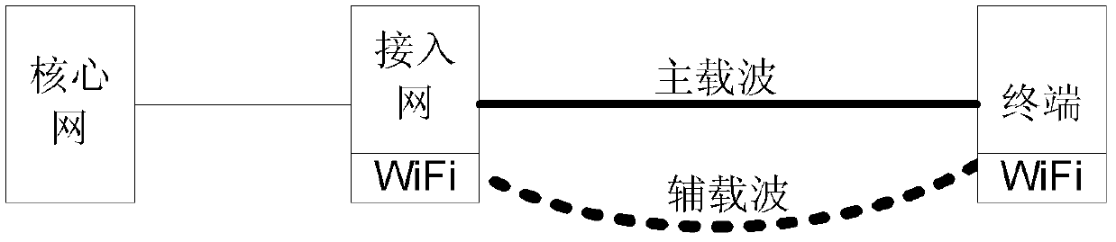
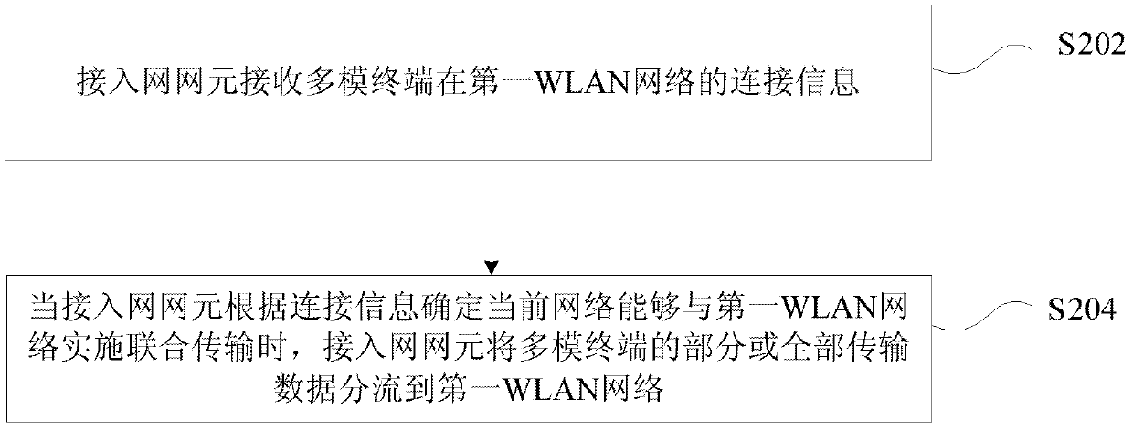
[0067] In this example, the 3GPP access network element receives the connection information of the multi-mode terminal on the WLAN network reported by the multi-mode terminal, and the 3GPP access network element offloads part or all of the transmission data of the multi-mode terminal to the WLAN network to realize multi-mode The modem terminal simultaneously transmits data through the combination of the 3GPP network and the WLAN network.
[0068] The 3GPP access network elements can be network element nodes of different 3GPP RAT access networks. For example, the radio access network element refers to eNB in the LTE network; the radio access network element refers to RNC and NodeB (collectively referred to as RNS) in the UMTS network. ; In the GSM network, the radio access network elements refer to BSC and B...
Embodiment 2
[0081] In this example, the LTE access network element eNB also integrates the WiFi access point function, and the UE is a multi-mode mobile phone that supports LTE and WLAN. For the specific process of the data transmission process, please refer to Figure 4 .
[0082] In step S402, the UE is in a connected state on the LTE network, and establishes a connection bearer with the eNB for data transmission.
[0083] Step S404, the UE discovers the existence of a WLAN network (that is, the first WLAN network) through scanning, and accesses the WLAN network through an existing procedure to establish an association with the WLAN network.
[0084] In step S406, the UE sends the connection information of the WLAN network to the eNB through an uplink message, such as a measurement report message, which includes information such as the BSSID of the WLAN network and the established association identifier AID.
[0085] Step S408, after the eNB receives it, it judges that the BSSID corres...
Embodiment 3
[0090] In this example, the network side includes the UMTS access network RNS and the WLAN network access point AP, and the UE is a multi-mode mobile phone that supports UMTS network and WLAN. For the specific flow of the data transmission process, see Figure 5 .
[0091] In step S502, the UE discovers a WLAN network (that is, the first WLAN network) through scanning, completes access to the WLAN network through an existing procedure, and performs service data transmission.
[0092] Step S504 , the UE needs to establish a service connection in the UMTS network where it resides due to upper-layer service requirements, so the UE initiates connection establishment to the UMTS access network RNS through a normal radio resource control connection establishment process.
[0093] Step S506, the UE sends the connection information of the WLAN network to the RNC through an uplink message, such as a radio resource control connection establishment complete message (RRC Connection Setup ...
PUM
 Abstract
Description
Claims
Application Information