Exhaust gas cooler

A technology of exhaust gas cooler and cooling cycle, applied in the direction of exhaust gas recirculation, exhaust gas treatment, exhaust device, etc., can solve the problems of high heat load, limited life of the shell, etc.

Inactive Publication Date: 2013-10-30
MAHLE INT GMBH
View PDF1 Cites 5 Cited by
  • Summary
  • Abstract
  • Description
  • Claims
  • Application Information

AI Technical Summary

Problems solved by technology

[0004] In exhaust gas coolers of known type extremely high thermal loads

Method used


Image

  • Exhaust gas cooler
  • Exhaust gas cooler
  • Exhaust gas cooler

Examples


Embodiment Construction

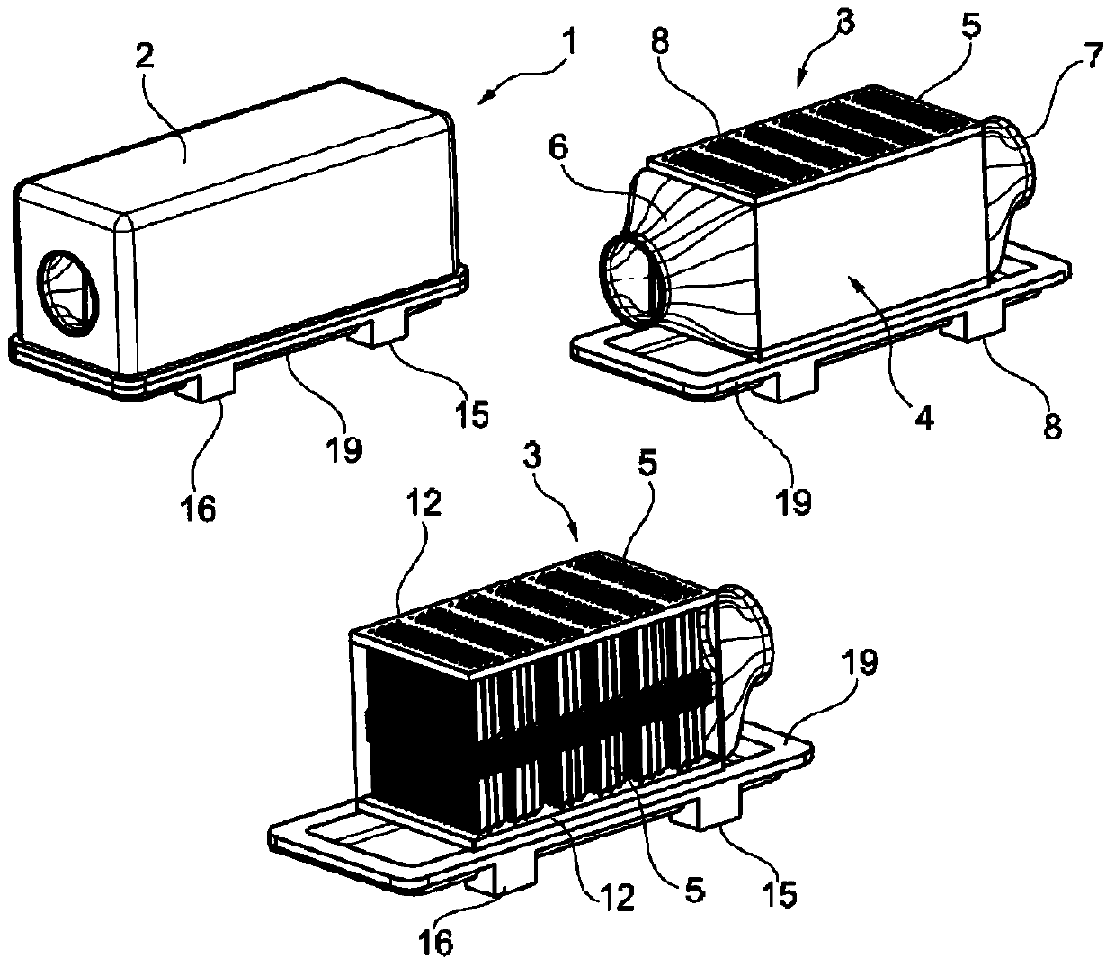
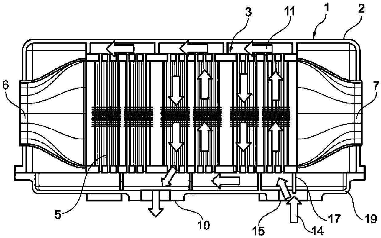
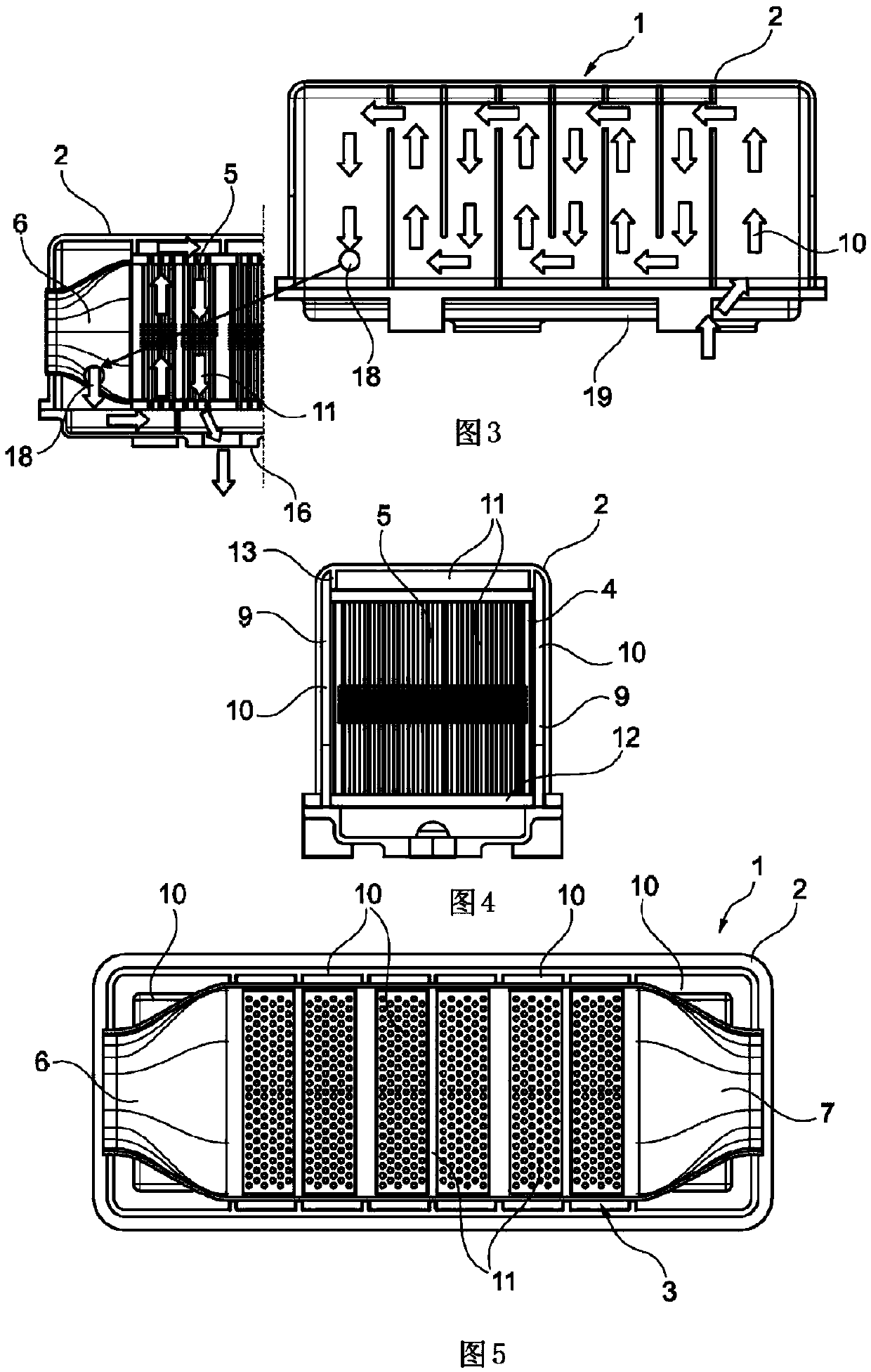
[0019] according to Figure 1-8 , the exhaust gas cooler 1 according to the invention has a housing 2 with a heat exchanger insert 3 arranged therein. The heat exchanger insert 3 has a plurality of tubes 5 around which the exhaust gas flows transversely in the inner shell 4 and in which tubes the cooling liquid of the first circuit 11 flows. The inner shell 4 generally has an inlet diffuser 6 and an outlet diffuser 7 as well as two side walls 8 . In order to reduce the thermal load on the housing 2 and at the same time achieve flexible, independent cooling, the solution of the invention uses a second cooling circuit 10 to cool at least partial regions of the housing 2 , especially the side walls 8 . The second cooling circuit 10 is independent of the first cooling circuit 11 . The inner shell 4 and the outer shell 2 can together form the pipes 9 for the second cooling circuit 10 or the outer shell 2 can be double-walled at least partially (see Figure 4 ), whereby the pipe ...


PUM


Abstract

The invention relates to an exhaust gas cooler (1) having an outer housing (2) and a heat exchanger insert (3) which is arranged therein and has pipes (5) around which exhaust gas flows transversely in an inner housing (4) and through which a coolant of a first cooling circuit (11) flows. It is essential to the invention that the outer housing (2) is cooled by a second cooling circuit (10) which is separate from the first cooling circuit (11). This in particular can reduce the temperature load.

Description

technical field [0001] The invention relates to an exhaust gas cooler with a heat exchanger insert arranged in a housing. Background technique [0002] DE 10 2008 011 557 A1 discloses a conventional exhaust gas cooler with a heat exchanger insert and a plurality of heat exchanger groups formed in one piece between the inflow area and the outflow area of ​​the exhaust gas. These heat exchanger assemblies comprise cooling tubes with cooling ribs and a heat exchanger insert surrounded by an inner shell, the side walls of which are arranged at a distance from the perforated side walls of the heat exchanger insert. Angled conduits for conveying cooling fluid from the cooling fluid inlet to the cooling fluid outlet through the heat exchanger bank are provided between the closed side wall of the heat exchanger insert and the adjacent side wall of the housing. Exhaust gas coolers are known to prevent overheating of the casing. [0003] DE 10 2008 1011 558 A1 discloses a heat excha...

Claims


Application Information

Patent Timeline
IPC IPC(8): F28D7/16F28F1/32F28F9/00
CPCF01N2240/02F28F1/32F28F9/001F28D7/1623F01N3/0205Y02T10/20F28D7/163F02M26/22Y02T10/12
Inventor 斯特芬·格罗青格马丁·帕尔曼亨宁·施罗德
Owner MAHLE INT GMBH
Why Eureka
Try Eureka