Optical intraocular pressure measuring apparatus and operating method thereof

A measuring device and intraocular pressure technology, which is applied in the direction of tonometer, medical science, eye testing equipment, etc., can solve the problems of quite long time consumption, prone to errors in measurement, and easy external force on the eyeball, so as to reduce time and avoid omissions or misplanting, and the effect of improving measurement efficiency

Active Publication Date: 2013-11-06
CRYSTALVUE MEDICAL
View PDF3 Cites 1 Cited by
  • Summary
  • Abstract
  • Description
  • Claims
  • Application Information

AI Technical Summary

Problems solved by technology

However, in the process of measuring the intraocular pressure of the living body with the current optical tonometry device, the eyeball is easily subjected to external force or vibrates by itself, which leads to errors in the measurement.
In addition, due to the limited measurement range of the current optical tonometry device, although continuous measurement in the depth direction can be performed at multiple points to complete two-dimensional or three-dimensional corneal data, it takes a long time to complete, and due to the measurement The target (eyeball) is often in a dynamic state, which will also cause the results measured by the optical tonometry device to not necessarily belong to the same measurement position, resulting in omission or misplacement of a certain section of corneal data

Method used


Image

  • Optical intraocular pressure measuring apparatus and operating method thereof
  • Optical intraocular pressure measuring apparatus and operating method thereof
  • Optical intraocular pressure measuring apparatus and operating method thereof

Examples


Embodiment Construction

[0039] A specific embodiment according to the present invention is an optical intraocular pressure measuring device. In this embodiment, the optical tonometry device uses optical interference technology to perform non-destructive and non-contact large-area measurement of the cornea of ​​a living body, so the thickness, curvature and deformation of the cornea can be measured at the same time. The measurement of parameters is used to obtain two-dimensional (surface) and three-dimensional (surface and longitudinal) corneal data, and can effectively eliminate the measurement error caused by the dynamic cornea in the prior art.

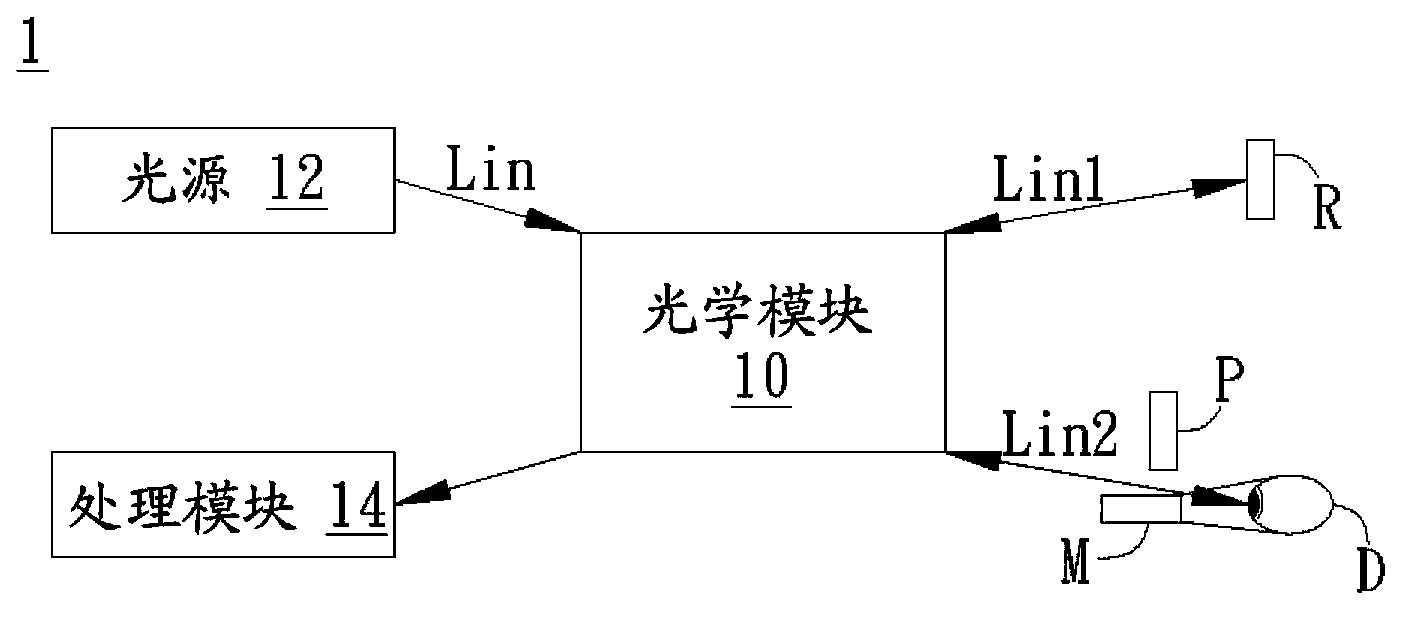
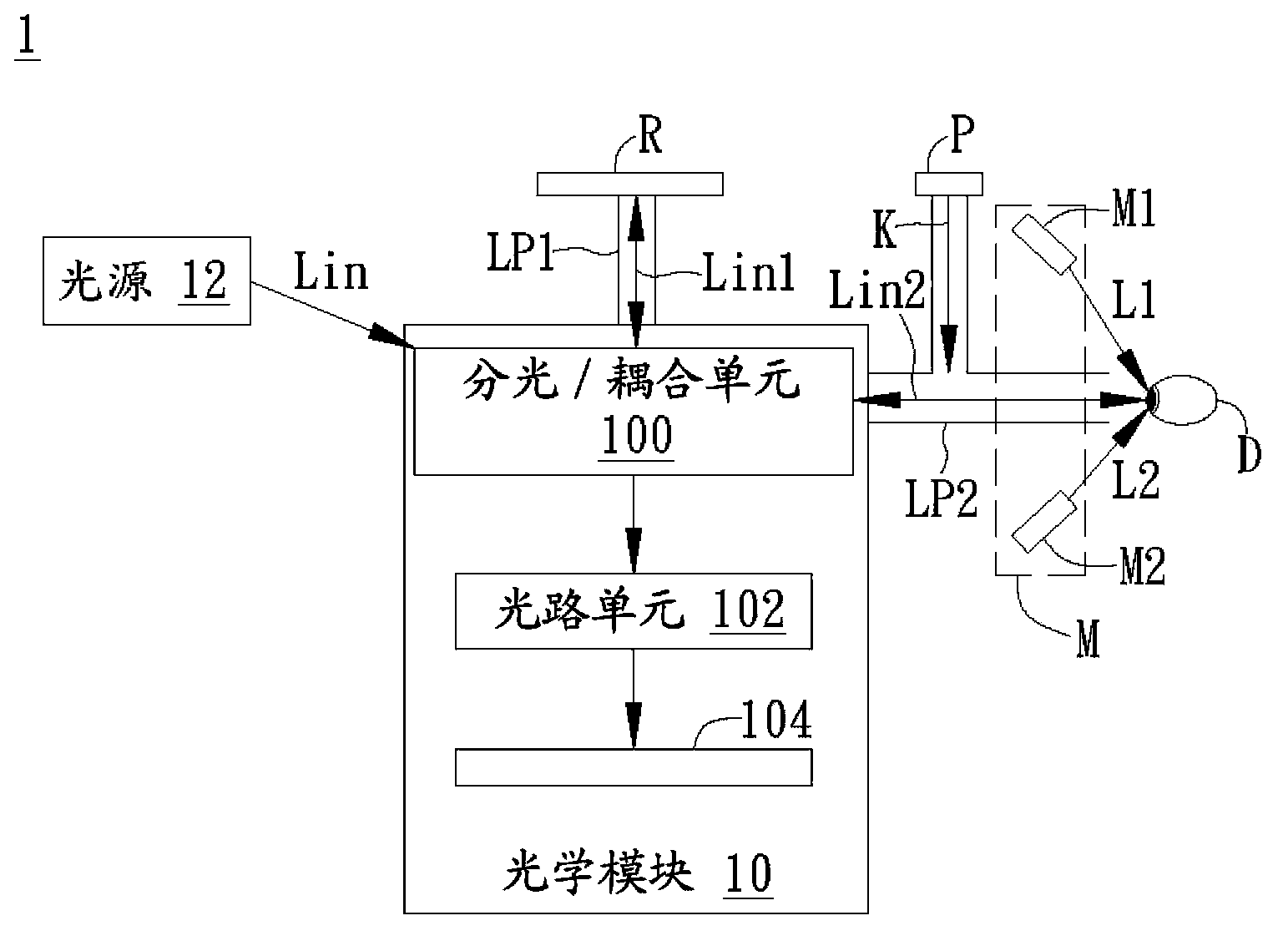
[0040] Please refer to figure 1 , figure 1 It is a schematic diagram of the optical tonometry device of this embodiment. Such as figure 1 As shown, the optical tonometry device 1 is a program for measuring an object D to be measured (such as an eyeball of a living body) through an optical interference technique. The optical tonometry device 1 includes ...


PUM


Abstract

An optical intraocular pressure measuring apparatus includes a light source, an optical module, a pressure providing module, a deformation measuring module, and a processing module. The light source provides an incident light. The optical module divides the incident light into a first incident light and a second incident light and emits them to a reference object and an object to be detected through a first light path and a second light path, and receives a first reflected light signal from reference object and a second reflected light signal from the object to be detected respectively. The pressure providing module coupled with second light path provides a pressure to deform the object to be detected. The deformation measuring module measures the deformation of the object to be detected. The processing module processes the first reflected light signal and second reflected light signal to generate an intraocular pressure measurement result.

Description

technical field [0001] The present invention is related to optical measurement, in particular to a non-contact optical intraocular pressure measuring device and its operation method. Background technique [0002] In recent years, with the continuous evolution of optical technology, optical interference technology provides a non-invasive method to understand the structure and composition of the target tissue. Due to its non-invasive characteristics, optical interference technology is widely used in human body functions testing and medical diagnosis. [0003] For example, the optical interferometry technique has been applied to the intraocular pressure measuring device of the living body. However, in the process of measuring the intraocular pressure of a living body by the current optical tonometry device, since the eyeball is easily subjected to external force or vibrates by itself, errors are likely to occur in the measurement. In addition, due to the limited measurement r...

Claims


Application Information

Patent Timeline
Patent Type & Authority Applications(China)
IPC IPC(8): A61B3/16
CPCA61B3/0008A61B3/16A61B3/165
Inventor 王威庄仲平颜孟新周忠诚黄文炜林俊男
Owner CRYSTALVUE MEDICAL
Why Eureka
Try Eureka