
Automatic paper laying machine

A paper laying and automatic technology, applied in the direction of winding strips, sending objects, packaging, etc., can solve the problems of low accuracy of manual paper laying, difficulty in aligning paper with glass, scratches or mildew resistance

Active Publication Date: 2015-10-21
CNBM TRIUMPH ROBOTICS SHANGHAI CO LTD
View PDF11 Cites 0 Cited by
  • Summary
  • Abstract
  • Description
  • Claims
  • Application Information

AI Technical Summary

Problems solved by technology

[0002] With the rapid development of my country's glass and plate industry, the demand for glass and plates in the market continues to increase. In order to prevent glass from being scratched or mildew-proof, glass cannot be in direct contact with each other. Therefore, between two adjacent layers of glass Spacers should be set up between two glass sheets. At present, powder spraying and paper laying are used. However, powder spraying is not only harmful to the human body, but the effect is not as good as that of paper laying. Therefore, most manufacturers use the method of laying paper between two pieces of glass.
Glass manufacturers generally use robots to stack glass and manually lay paper. Manually place a piece of glass and lay a piece of paper. This not only wastes manpower, but also has low precision and uneven paper laying. It is difficult for paper to align with glass. The most important thing is humans and robots. It is very unsafe to work together, there is a possibility of personal injury or even death
At the same time, the layout of many glass factories is compact, which is not suitable for the operation of large paper laying equipment

Method used


Image

  • Automatic paper laying machine

Examples


Embodiment Construction

[0024] In order to understand the technical content of the present invention more clearly, the following examples are given in detail.

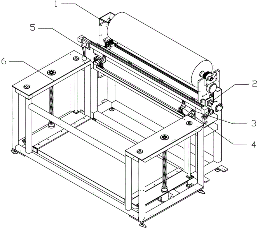
[0025] The automatic paper laying machine includes an unwinding mechanism 1 and a paper feeding mechanism 2, the output end of the unwinding mechanism 1 is connected with the paper feeding mechanism 2, the output end of the paper feeding mechanism 2 is connected with the lifting platform 6, and the paper feeding mechanism 2 An air blowing mechanism 3 is provided at the output end of the paper blowing mechanism 3, a paper cutting mechanism 5 is arranged above the blowing mechanism 3, and a paper feeding mechanism 2 includes a paper thickness adjusting device.

[0026] The unwinding mechanism 1 includes a drum core, on which the paper is wound, the upper gear is fixedly connected to one end of the drum core, the lower gear is fixedly connected to the output shaft of the magnetic powder brake, and the upper gear and the lower gear are meshed, and...


PUM


Abstract

The invention relates to an automatic paper paving machine, comprising an unreeling mechanism and a paper conveying mechanism, wherein the output end of the unreeling mechanism is connected with the paper conveying mechanism; the output end of the paper conveying mechanism is connected with a lifting platform; a blowing mechanism is arranged at the output end of the paper conveying mechanism; a paper cutting mechanism is arranged above the blowing mechanism; the paper conveying mechanism comprises a paper sheet thickness adjusting device. According to the automatic paper paving machine with the structure, a drive roller and a driven roller in the paper conveying mechanism are good in a pressing effect, paper sheets conveyed are flat and do not easily deflect, the paper paving precision is high, the driven roller and the drive roller can automatically adapt to the paper sheets with different thickness through a spring, and the universality is strong; the lifting platform is integrated with the paper conveying mechanism, the space is greatly saved, the blowing mechanism is used for assisting in conveying the paper sheets and preventing the paper sheets from flying up or stopping; a paper knife in the paper cutting mechanism is circular, the cutting is very rapid, and the cutting edge of the paper knife is lower than the surfaces of the paper sheets, so that two edges of the paper sheets can be completely cut off.

Description

technical field [0001] The invention relates to the technical field of paper laying machines, in particular to an automatic paper laying machine. Background technique [0002] With the rapid development of my country's glass and plate industry, the demand for glass and plates in the market continues to increase. In order to prevent glass from being scratched or mildew-proof, glass cannot be in direct contact with each other. Therefore, between two adjacent layers of glass Spacers need to be set between two pieces of glass. At present, powder spraying and paper laying are used. However, powder spraying is not only harmful to the human body, but the effect is not as good as that of paper laying. Therefore, most manufacturers use the method of laying paper between two pieces of glass. Glass manufacturers generally use robots to stack glass and manually lay paper. Manually place a piece of glass and lay a piece of paper. This not only wastes manpower, but also has low precision a...

Claims


Application Information

Patent Timeline
Patent Type & Authority Patents(China)
IPC IPC(8): B65B61/22B65H20/02B65H35/06
Inventor 张显山陆定军姚铁军吴骁斌黄祥
Owner CNBM TRIUMPH ROBOTICS SHANGHAI CO LTD
Learn More