Rotary type viscous fluid damper

A viscous fluid, rotary technology, applied in the direction of building components, shockproof, etc., can solve the problems of poor anti-torsional vibration performance, increase construction cost, large length and other problems, achieve good vibration performance and reduce construction cost

Inactive Publication Date: 2013-11-13
刘康安
View PDF6 Cites 28 Cited by
  • Summary
  • Abstract
  • Description
  • Claims
  • Application Information

AI Technical Summary

Problems solved by technology

[0004] At present, the known viscous fluid damper is a piston rod type in structure, and its length is relatively large. It is limited in volume when installed in a narrow space, and only small dampers with poor damping effect can be used, which may easily lead to failure of the construction site. Shock absorption (vibration) design requirements; the existing viscous fluid dampers have poor anti-torsional vibration performance, and in order to achieve the construction effect, the number of viscous fluid dampers is usually increased, resulting in increased construction costs

Method used


Image

  • Rotary type viscous fluid damper
  • Rotary type viscous fluid damper
  • Rotary type viscous fluid damper

Examples


Embodiment 1

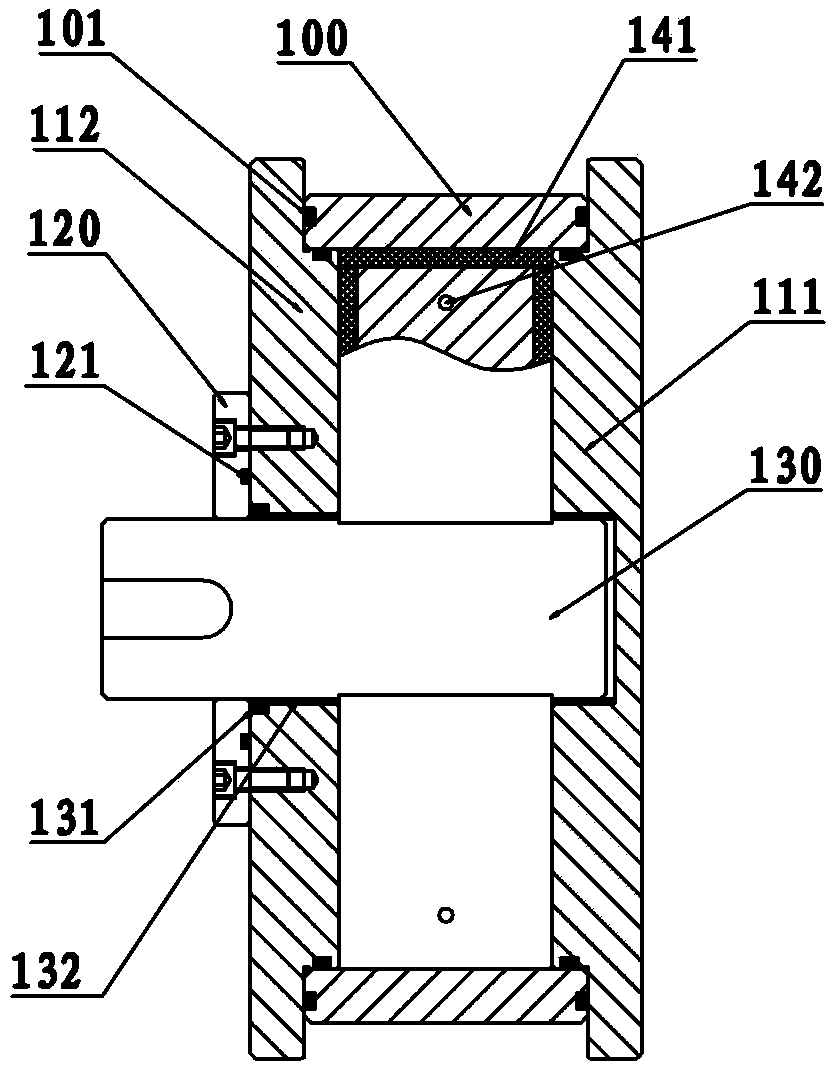
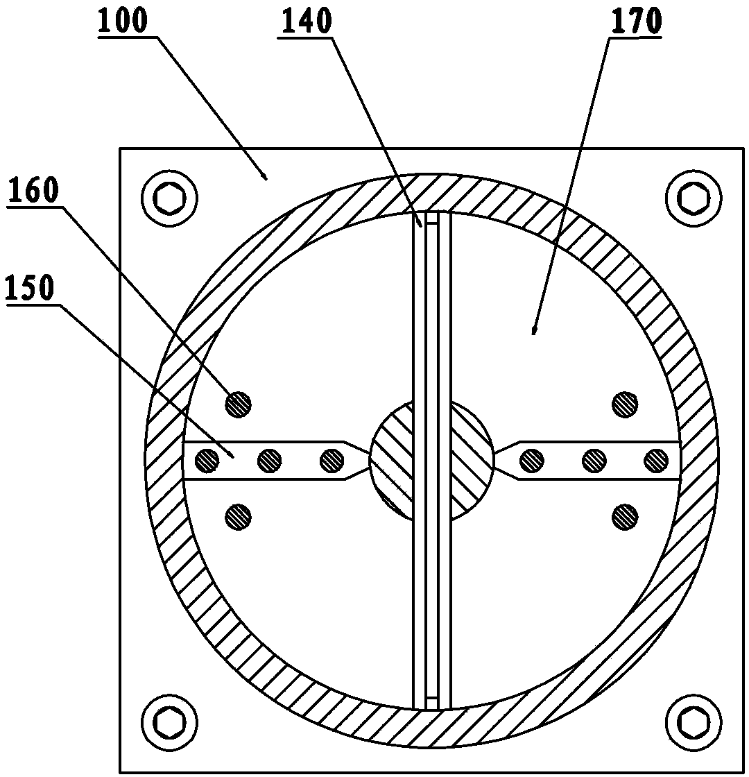
[0018] Such as figure 1 , figure 2 As shown, this embodiment discloses a rotary viscous fluid damper, including a cylinder 100, a front guide sleeve 112, a rear guide sleeve 111, a sub-chamber block 150, a rotating blade 140, and a rotating shaft 130; the front guide sleeve 112, Rear guide sleeves 111 are respectively mounted on the front and rear corresponding ends of the cylinder body 100 to form a closed space; rotating blades 140, rotating shafts 130, and sub-cavity blocks 150 are simultaneously arranged in the enclosed space; one end of the rotating shaft 130 passes through the front guide sleeve 112, the other end is movably connected with the center point of the rear guide sleeve 111; the rotating blade 140 is installed on the side of the rotating shaft 130; A space of equal volume; a damping hole 142 is opened on the rotating blade 140; the damping medium 170 is filled in the sealed space.

[0019] This embodiment is uniquely designed with a rotary viscous fluid dam...

Embodiment 2

[0021] Such as figure 1 , figure 2 As shown, this embodiment discloses a rotary viscous fluid damper with better sealing effect. , which includes a cylinder block 100, a front guide sleeve 112, a rear guide sleeve 111, a sub-cavity block 150, a rotating blade 140, and a rotating shaft 130; , and a sealing ring 101 is installed at each contact position to form a closed space; the rotating blade 140, the rotating shaft 130, and the sub-cavity block 150 are simultaneously arranged in the closed space; one end of the rotating shaft 130 passes through the center point of the front guide sleeve 112, The other end is movably connected with the central point of the rear guide sleeve 111, and a sliding bearing 132 and an oil seal 131 are installed at the contact position between the rotating shaft 130 and the front guide sleeve 112; 120 is fixed on the left side of the front guide sleeve 112 by screws, and a sealing ring 121 is arranged on the contact surface between the two; A sea...

Embodiment 3

[0024] Such as figure 1 , figure 2 As shown, this embodiment discloses a rotary viscous fluid damper with longer service life, which includes a cylinder body 100, a front guide sleeve 112, a rear guide sleeve 111, a sub-chamber block 150, a rotating blade 140, and a rotating shaft 130; The guide sleeve 112 and the rear guide sleeve 111 are respectively mounted on the front and rear corresponding ends of the cylinder body 100 to form a closed space; the rotating blade 140, the rotating shaft 130 and the sub-chamber block 150 are simultaneously arranged in the closed space; one end of the rotating shaft 130 is passed through The center point of the front guide sleeve 112 is passed, and the other end is movably connected with the center point of the rear guide sleeve 111; the rotating blade 140 is installed on the side of the rotating shaft 130; The enclosed space is divided into spaces of equal volume; a damping hole 142 is opened on the rotating blade 140; a damping medium 17...


PUM


Abstract

The invention relates to the design field of dampers, in particular to a rotary type viscous fluid damper, which comprises a cylinder body, a front guide sleeve, a rear guide sleeve, a cavity dividing block, a rotary blade and a rotary shaft, wherein the front guide sleeve and the rear guide sleeve are respectively arranged on front and back ends of the cylinder body so as to form a closed space; the rotary blade, the rotary shaft and the cavity dividing block are simultaneously arranged in the closed space; one end of the rotary shaft penetrates through a central point of the front guide sleeve; the other end of the rotary shaft is movably connected with a central point of the rear guide sleeve; the rotary blade is arranged on the side face of the rotary shaft; the cavity dividing block is simultaneously connected with the front guide sleeve and the rear guide sleeve, and divides the closed space into spaces with equal volume; damping holes are arranged on the rotary blade; and damping medium are filled in the closed space. Through applying the technical scheme, the damping effect is better, and the size is smaller.

Description

technical field [0001] The invention relates to the field of damper design, in particular to a rotary viscous fluid damper. Background technique [0002] Energy dissipation and shock absorption technology is to design some non-load-bearing components of the structure as energy dissipation components, or to set up effective components in certain parts of the structure; when the wind or small earthquake occurs, the structure is in an elastic state, and the energy dissipation components or energy dissipation components It can increase the stiffness of the structure; in rare earthquakes, the energy-dissipating components or energy-dissipating components will generate greater damping and consume seismic energy, thereby reducing the dynamic response of the main structure and avoiding the large plastic deformation of the main structure. destroy. At present, the main energy dissipation components that have been developed at home and abroad include: various types of friction damper...

Claims


Application Information

Patent Timeline
Patent Type & Authority Applications(China)
IPC IPC(8): E04B1/98
Inventor 刘康安莫凡芒
Owner 刘康安
Why Eureka
Try Eureka