Method and equipment for filling liquid in temperature sensing bulb of thermostatic expansion valve

A thermal expansion valve and temperature-sensing bulb technology, which is applied in lighting and heating equipment, refrigeration and liquefaction, and fluid circulation arrangements, can solve the problems of short service life of thermal expansion valves, poor filling quality of temperature-sensing bulbs, and uneven product quality. Qi and other problems, to achieve the effect of reliable sealing performance, long service life and simple equipment structure

Inactive Publication Date: 2013-11-13
浙江金丰机械设备有限公司
View PDF6 Cites 9 Cited by
  • Summary
  • Abstract
  • Description
  • Claims
  • Application Information

AI Technical Summary

Problems solved by technology

Therefore, the charging quality of the refrigerant in the temperature sensing bulb of the thermal expansion valve is particularly important. The traditional method adopts manual charging, and the amount of refrigerant charging in the temperature sensing bulb varies from person to person, resulting in the charging of the temperature sensing bulb. Poor injection quality, high failure rate during use, uneven quality of the same batch of products and poor consistency; in addition, after the traditional temperature sensing bulb is filled, the nozzle of the capillary adopts a mechanically flattened sealing form. The thermal expansion valve has a short service life. When it is used for a long time, it is prone to air leakage at the sealing port. After the temperature sensing package leaks, it can only be replaced with a new thermal expansion valve.

Method used


Image

  • Method and equipment for filling liquid in temperature sensing bulb of thermostatic expansion valve
  • Method and equipment for filling liquid in temperature sensing bulb of thermostatic expansion valve
  • Method and equipment for filling liquid in temperature sensing bulb of thermostatic expansion valve

Examples


Embodiment

[0027] A liquid filling method for a temperature sensing bulb of a thermal expansion valve in this embodiment includes the following steps:

[0028] Step a: Vacuumize the inside of the thermal expansion valve temperature sensing bulb to -1MPa;

[0029] Step b: Fill 0.5 MPa of refrigerant into the temperature sensing bulb of the thermal expansion valve;

[0030] Step c: Flatten the capillary filling end of the thermal expansion valve about 1 cm from the mouth of the tube to seal it;

[0031] Step d: welding and sealing the nozzle of the capillary filling end of the thermal expansion valve.

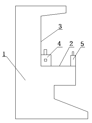
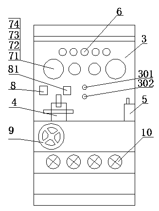
[0032] The equipment used in the above charging method, such as figure 1 , figure 2 As shown, the device body 1 is included, the front side of the device body 1 is provided with a horizontal workbench 2, a control panel 3 vertically arranged with the workbench 2, and a filling tool 4 is fixedly arranged on one side of the workbench 2, and another A welding station 5 is arranged on one ...


PUM


Abstract

The invention discloses a method and equipment for filling liquid in a temperature sensing bulb of a thermostatic expansion valve. The method comprises the steps of a) vacuumizing the internal part of the temperature sensing bulb of the thermostatic expansion valve; b) filling refrigerant into the temperature sensing bulb of the thermostatic expansion valve; c) flattening the position of the filling end of the capillary tube of the thermostatic expansion valve in a stamping way to enable the filling end to be sealed, wherein the position is approximately 1cm far away from the mouth of the capillary tube; and d) welding and sealing the mouth of the filling end of the capillary tube of the thermostatic expansion valve. The equipment comprises an equipment main body. A worktable and a control panel are arranged on the front side of the equipment main body. A filling tooling and a welding station are arranged on the worktable. A welding machine, a vacuum pump, a refrigerant storage tank and an air compressor which are connected with the filling tooling are arranged in the worktable. Since the filling process disclosed by the invention is added with a capillary tube mouth welding and sealing process relative to the prior art, the product performance is enabled to be more reliable and the product service life is longer; and the structure of the filling equipment is simple, the automation level is high, the equipment is simple to operate and the filling accuracy is high.

Description

technical field [0001] The invention relates to a liquid filling method and equipment for a temperature-sensing bulb of a thermal expansion valve. Background technique [0002] The thermal expansion valve is an important part of the refrigeration device. It realizes the throttling from the condensing pressure to the evaporating pressure, and controls the flow of the refrigerant at the same time; although its volume is small, it has a huge effect. Its work quality directly determines the operation of the entire system The quality of work is to supply liquid to the evaporator in the best way to ensure that the superheat of the refrigerant vapor at the outlet of the evaporator is stable. The temperature sensing bulb of the thermal expansion valve must be in good contact with the suction pipe of the compressor to accurately sense the suction temperature of the compressor. It is usually filled with the same refrigerant as that in the refrigeration system, so as to achieve feedbac...

Claims


Application Information

Patent Timeline
Patent Type & Authority Applications(China)
IPC IPC(8): F25B45/00F25B41/06F25B41/31F25B41/37
Inventor 何立伟徐波江爱军项世长林志良
Owner 浙江金丰机械设备有限公司
Why Eureka
Try Eureka