Online sub-pixel optical component damage detection method based on radiation calibration

A technology of optical components and detection methods, which is applied in the direction of optical testing flaws/defects, etc., which can solve the problems of high-precision damage size, inability to obtain online detection images, etc.

Active Publication Date: 2013-11-13
HARBIN INST OF TECH
View PDF3 Cites 14 Cited by
  • Summary
  • Abstract
  • Description
  • Claims
  • Application Information

AI Technical Summary

Problems solved by technology

[0003] The present invention aims to solve the problem that the existing online detection method cannot obtain the high-precision size of the damage in the online detection image, and provides an online detection method for sub-pixel optical element damage based on radiation calibration

Method used


Image

  • Online sub-pixel optical component damage detection method based on radiation calibration
  • Online sub-pixel optical component damage detection method based on radiation calibration
  • Online sub-pixel optical component damage detection method based on radiation calibration

Examples


specific Embodiment approach 1

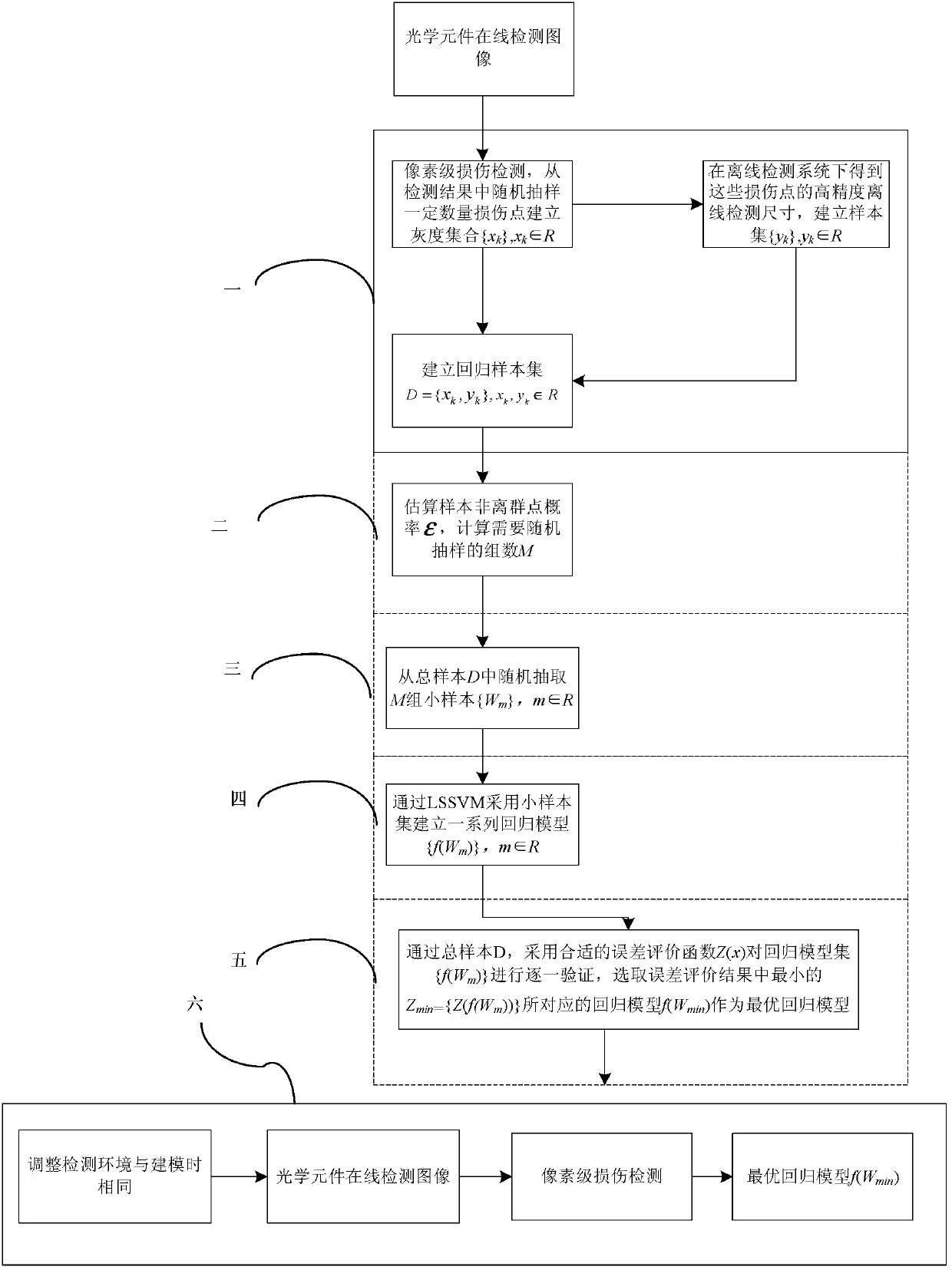
[0038] Specific Embodiment 1: The online detection method for sub-pixel optical element damage based on radiation calibration in this embodiment includes the following contents:

[0039]1. After obtaining the total gray level of all damaged areas of the optical element through the traditional online detection method, randomly select N damaged areas, obtain the accurate size of the damaged area in the offline detection system, and establish a sample set

[0040] D={(x 1 ,y 2 ),...., (x k ,y k ),...., (x N ,y N )}, x k ,y k ∈R; where x k is the total gray level of each damage area in the online image, y k High-precision size obtained under high-precision off-line system for the damage area;

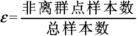
[0041] 2. Estimate the probability of non-outlier points in the sample set ε, through the formula Calculate the number of groups M that need to be randomly sampled;

[0042] 3. Randomly select M groups of small samples from the sample set D {W 1 (x 1,1 ,y 1,1 ,...,x 1,I ,y ...

specific Embodiment approach 2

[0076] Specific embodiment 2: The difference between this embodiment and specific embodiment 1 is that the non-outlier probability ε in the step 2 is defined as:

[0077]

[0078] Generally, the exact value of ε of the sample cannot be obtained, but its approximate value can be obtained by analyzing the original data. Unlike the general RANSAC method, the minimum number of samples I used to establish the LSSVM model is only related to the quality of the sample, and the appropriate I can be obtained through experiments. . Other steps and parameters are the same as those in Embodiment 1.

specific Embodiment approach 3

[0079] Specific embodiment three: the difference between this embodiment and specific embodiment one or two is that a series of LSSVM regression models established in the step four are expressed as constrained optimization problems:

[0080] min w , b , e J ( ω , e ) = 1 2 | | ω | | 2 + γ 2 Σ k = 1 N e k 2

[0081]

[0082] in is a nonlinear mapping function, transforming the linear inseparable problem into a linear problem in high-dimensiona...


PUM


Abstract

The invention provides an online sub-pixel optical component damage detection method based on radiation calibration, which relates to the field of online optical component detection, and in particular relates to a quick online detection method of a large-caliber optical component of a large optical system. The online detection method can solve the problem that the high-precision size of a damage in an online detection picture cannot be acquired by an existing online detection method, and comprises the following steps: 1, establishing a sample set; 2, estimating the probability epsilon of a non-outlier of the sample set; 3, randomly extracting M groups of small samples from the sample set D; 4, establishing a series of LSSVM (least squares support vector machine) regression models f(W1),..., f(Wm),..., f(WM) by a cross validation method; and 5, selecting a proper error evaluation function Z(x) through the sample set D to verify the regression models f(W1),..., f(Wm),..., f(WM) one by one, thus acquiring the high-precision sub-pixel size of the whole damage area. The method can be applied to the field of online optical component detection.

Description

technical field [0001] The invention relates to the field of on-line detection of optical elements, in particular to a method for rapid on-line detection of large-diameter optical elements in a large optical system. Background technique [0002] In the online inspection system of optical components in large optical systems, due to the limitation of imaging resolution, it is difficult to meet the increasingly higher inspection accuracy requirements only through traditional pixel-level image processing methods. In addition, due to cross-pixel imaging and other reasons, the image of the damaged area on the CCD is generally larger than the theoretical size, and this error has a great impact on the detection accuracy of small-sized damaged areas. Some damaged areas whose size is smaller than the pixel equivalent of the imaging system are even larger than 1 pixel in the detection image. The traditional pixel-level optical element damage image processing method works well for the ...

Claims


Application Information

Patent Timeline
Patent Type & Authority Applications(China)
IPC IPC(8): G01N21/88
Inventor 刘国栋冯博刘炳国庄志涛卢丙辉
Owner HARBIN INST OF TECH
Why Eureka
Try Eureka