

Method and system for forecasting tunnel geology
A geological forecasting and geological technology, applied in geophysical surveying, instruments, etc., can solve problems such as single survey method, potential safety hazards in tunnel construction, inability to accurately predict tunnel geological conditions, etc., and achieve the effect of strong reliability and improved practicability
- Summary
- Abstract
- Description
- Claims
- Application Information
AI Technical Summary
Problems solved by technology
Method used
Image

Examples
Embodiment Construction
[0016] Hereinafter, the present invention will be described in detail with reference to the drawings and examples. It should be noted that, in the case of no conflict, the embodiments in the present application and the features in the embodiments can be combined with each other.
[0017] In order to optimize the survey technology of tunnel geology, obtain more accurate survey results, provide reliable data for tunnel construction, and improve the safety of tunnel construction, embodiments of the present invention provide a method and system for predicting tunnel geology.
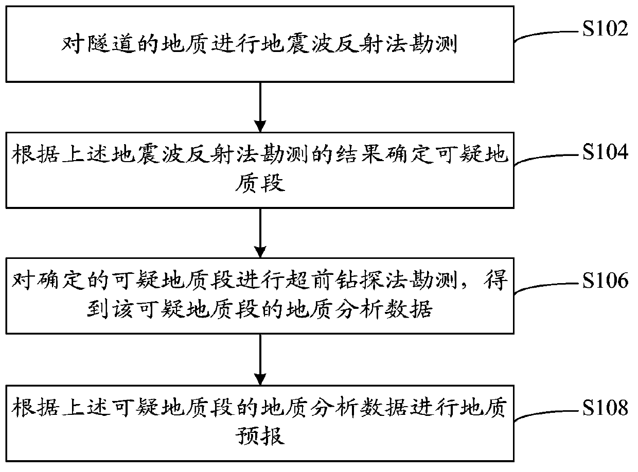
[0018] Such as figure 1 The flow chart of the prediction method of tunnel geology shown, the method includes the following steps:
[0019] Step S102, performing seismic wave reflection survey on the geology of the tunnel;
[0020] Step S104, determining suspicious geological sections according to the survey results of the above-mentioned seismic wave reflection method;
[0021] Step S106, performing advan...
PUM
 Abstract
Description
Claims
Application Information